Circuit Symbols
Drawing style

Switch symbol

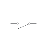
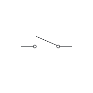
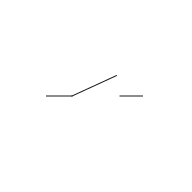
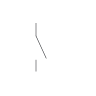
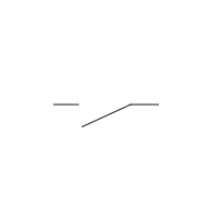
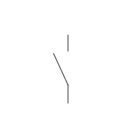
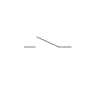
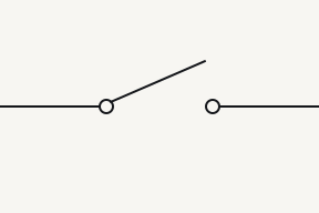
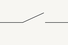
A switch symbol is a contact that makes or breaks a path. Poles count the circuits it switches; throws count the contacts each pole can close onto. In the drawings here every contact is drawn at rest: a normally-open button open, a normally-closed one closed.⁠Source 1

Reference Designator S⁠Source 2

On this sheet

Symbol and what it is doing

US style

IEC style

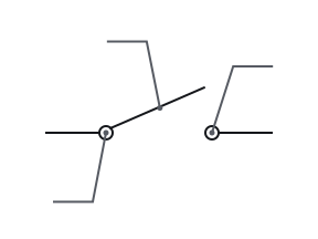
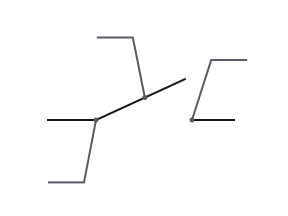
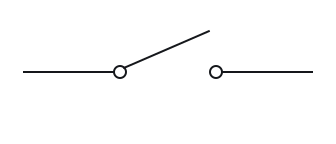
Fig. 1 — Switch (SPST), position open: No path Switch (SPST), position closed: One node
12
Fig. 1a — Switch (SPST), position open: No path
12
Fig. 1b — Switch (SPST), position closed: One node
12
Fig. 1a — Switch (SPST), position open: No path
12
Fig. 1b — Switch (SPST), position closed: One node

Close the switch, then press each button. The drawings stay at rest; the highlight shows where current can pass now.

Position

No path. Under the ideal-contact model, an open switch breaks the conducting path between its two terminals.

One node. Under the ideal-contact model, a closed switch joins its two terminals with zero contact resistance; they are at the same potential.

A switch symbol stands for a contact that either completes or breaks a path.

Terminals

12
A single-pole, single-throw (SPST) switch has two terminals. Their left or right position on the page does not give them different electrical roles.⁠Source 1

Parts of the drawing

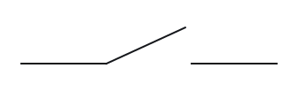
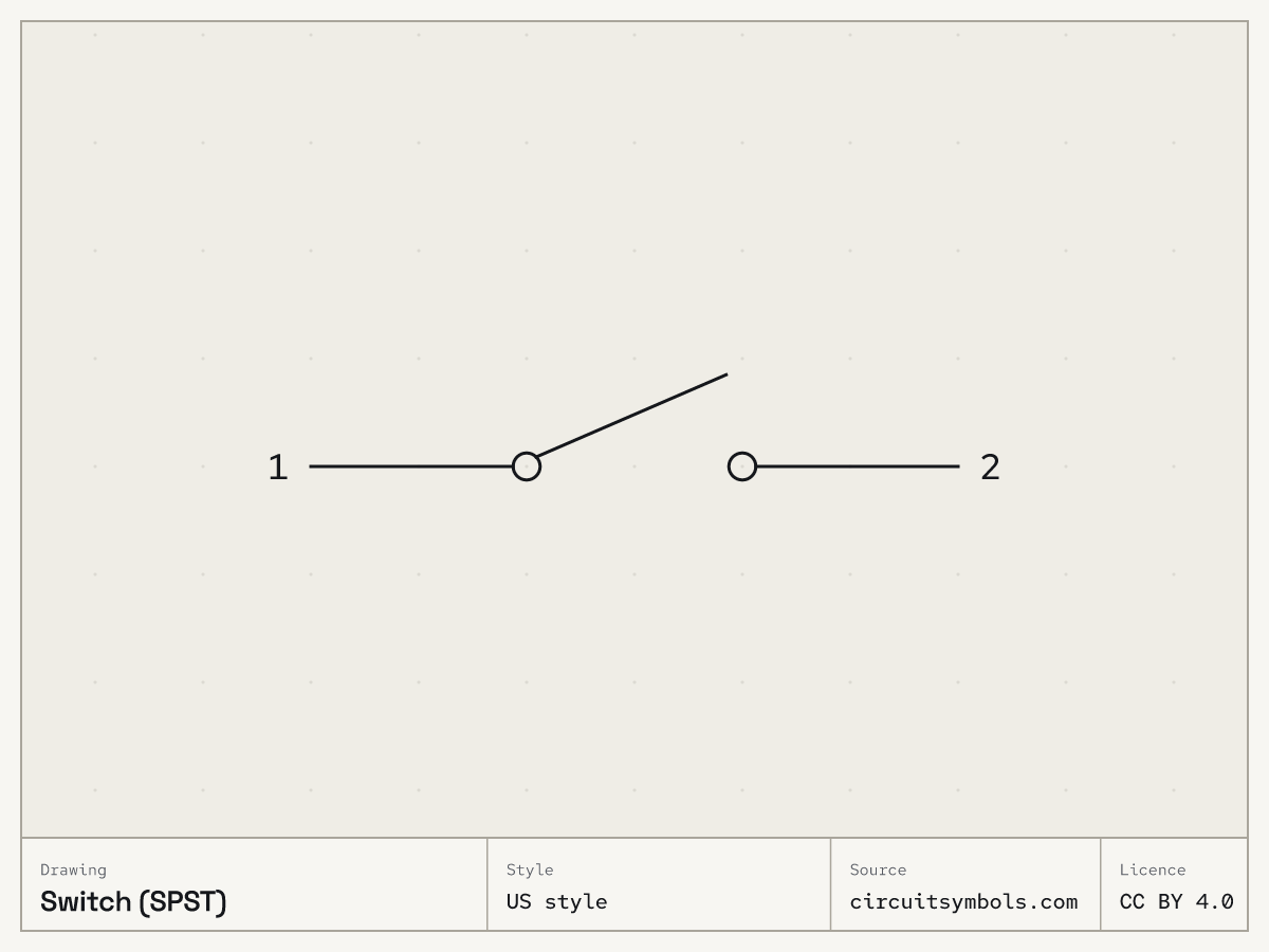
  • SPST switch symbol in US style, with numbered leaders to the moving arm, the fixed contact and the small circles
1 Moving arm
2 Fixed contact
In a switch symbol the moving arm is the pole, and each fixed contact it can close onto is a throw.⁠Source 1Source 3
3 Small circles
In this sheet's switch drawings, small circles or bare line ends mark the contact points. These are drawing details; follow the moving arm and terminal connections to identify the switch.⁠Source 1Source 4
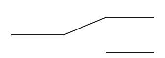
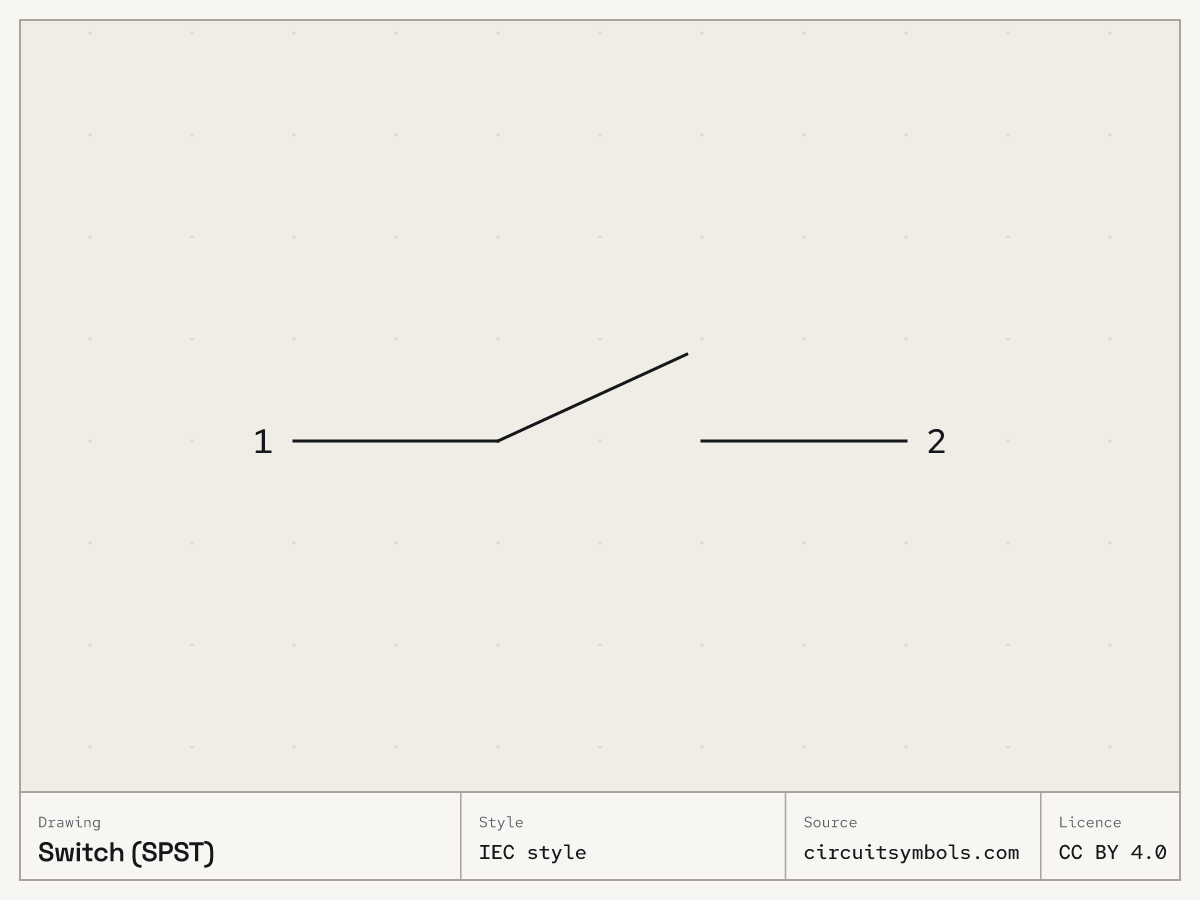
  • SPST switch symbol in IEC style, with numbered leaders to the moving arm, the fixed contact and the bare line ends
1 Moving arm
2 Fixed contact
In a switch symbol the moving arm is the pole, and each fixed contact it can close onto is a throw.⁠Source 1Source 3
3 Bare line ends
In this sheet's switch drawings, small circles or bare line ends mark the contact points. These are drawing details; follow the moving arm and terminal connections to identify the switch.⁠Source 1Source 4
Fig. 2 — SPST switch symbol, US style, its marks numberedSPST switch symbol, IEC style, its marks numbered
  • Switch (SPST) symbol, US style, turned 0°, with its terminal names attached

    0°

  • Switch (SPST) symbol, US style, turned 90°, with its terminal names attached

    90°

  • Switch (SPST) symbol, US style, turned 180°, with its terminal names attached

    180°

  • Switch (SPST) symbol, US style, turned 270°, with its terminal names attached

    270°

  • Switch (SPST) symbol, US style, mirrored, with its terminal names attached

    Mirrored

Rotating or mirroring a whole symbol, with its terminal identities and connections preserved, does not change the component. The terminal labels move with the drawing.⁠Source 5

  • Switch (SPST) symbol, IEC style, turned 0°, with its terminal names attached

    0°

  • Switch (SPST) symbol, IEC style, turned 90°, with its terminal names attached

    90°

  • Switch (SPST) symbol, IEC style, turned 180°, with its terminal names attached

    180°

  • Switch (SPST) symbol, IEC style, turned 270°, with its terminal names attached

    270°

  • Switch (SPST) symbol, IEC style, mirrored, with its terminal names attached

    Mirrored

Rotating or mirroring a whole symbol, with its terminal identities and connections preserved, does not change the component. The terminal labels move with the drawing.⁠Source 5

Fig. 3 — Switch (SPST) symbol, US style at 0°, 90°, 180° and 270°, and mirroredSwitch (SPST) symbol, IEC style at 0°, 90°, 180° and 270°, and mirrored

Variants

A toggle-style switch arm is hinged at one fixed contact and swings to the other. A push button's moving bar bridges both fixed contacts at once, with no hinge at either end.⁠Source 6

  • 12
    12

    Push button, normally open

    The momentary push buttons shown here change contact state while pressed and return to their drawn, unactuated state when released.⁠Source 1

  • 12
    12

    Push button, normally closed

    Switch contacts are drawn in their normal status: the position they rest in with no force applied. A normally-open (NO) contact is drawn open and a normally-closed (NC) contact closed; for a momentary push button, normal means not pressed.⁠Source 1

  • COM12
    COM12
    Switch (SPDT)
    COM11A1BCOM22A2B
    COM11A1BCOM22A2B
    Switch (DPDT)

    Switch (SPDT) and switch (DPDT)

    Poles count the separate circuits a switch controls; throws count the contact destinations available to each pole. An off position is not an additional throw.⁠Source 1

    COM (SPDT); COM1, COM2 (DPDT)
    In a double-throw switch the common terminal is the one the moving arm belongs to.⁠Source 1
    1, 2 (SPDT); 1A, 1B, 2A, 2B (DPDT)
    Each throw terminal is one of the positions the arm can connect the common terminal to.⁠Source 1

What the variants are doing

Normally open push button

12
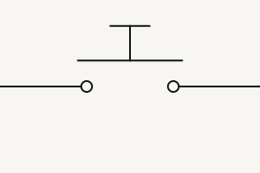
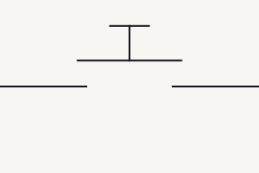
Fig. 4 — Push button, normally open, button released: No path Push button, normally open, button pressed: Closed path
12
Fig. 4 — Push button, normally open, button released: No path Push button, normally open, button pressed: Closed path
12
Fig. 4a — Push button, normally open, button released: No path
12
Fig. 4b — Push button, normally open, button pressed: Closed path
12
Fig. 4a — Push button, normally open, button released: No path
12
Fig. 4b — Push button, normally open, button pressed: Closed path
Button

No path. Under the momentary-switch model, the normally-open push button is open when released: its two terminals have no conducting path.

Closed path. Under the momentary-switch model, pressing the normally-open push button closes its contacts and joins its two terminals.

Normally closed push button

12
Fig. 5 — Push button, normally closed, button released: Closed path Push button, normally closed, button pressed: No path
12
Fig. 5 — Push button, normally closed, button released: Closed path Push button, normally closed, button pressed: No path
12
Fig. 5a — Push button, normally closed, button released: Closed path
12
Fig. 5b — Push button, normally closed, button pressed: No path
12
Fig. 5a — Push button, normally closed, button released: Closed path
12
Fig. 5b — Push button, normally closed, button pressed: No path
Button

Closed path. Under the momentary-switch model, the normally-closed push button is closed when released: its contacts join the two terminals.

No path. Under the momentary-switch model, pressing the normally-closed push button opens its contacts and breaks the path between its terminals.

Often confused with

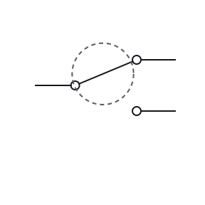
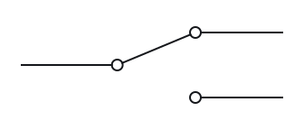
    • Switch (SPDT) symbol in US style; ringed: one arm

      Switch (SPDT)

      One arm

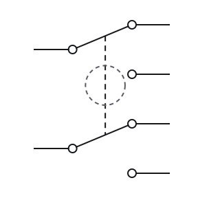
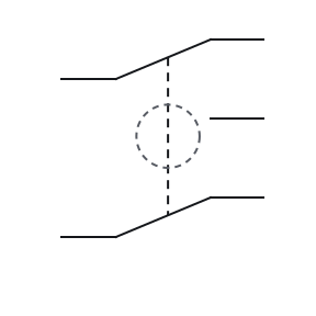
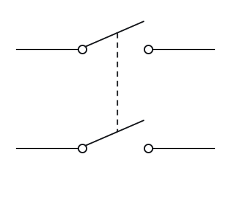
    • Switch (DPDT) symbol in US style; ringed: two arms tied by a dashed link

      Switch (DPDT)

      Two arms tied by a dashed link

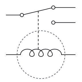
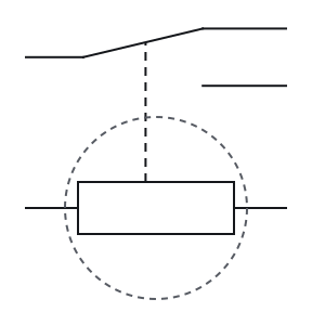
    • Relay (coil and SPDT contact) symbol in US style; ringed: coil linked to its contacts

      Relay (coil and SPDT contact)

      Coil linked to its contacts

    Count the arms and look for a coil: an SPDT switch has one arm between two fixed contacts, a DPDT switch has two arms tied by a dashed link, and a relay adds a coil linked to its contacts.⁠Source 1Source 6Source 7

    • Switch (SPDT) symbol in IEC style; ringed: one arm

      Switch (SPDT)

      One arm

    • Switch (DPDT) symbol in IEC style; ringed: two arms tied by a dashed link

      Switch (DPDT)

      Two arms tied by a dashed link

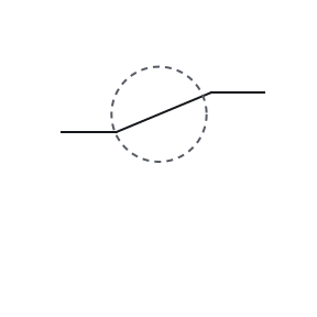
    • Relay (coil and SPDT contact) symbol in IEC style; ringed: coil linked to its contacts

      Relay (coil and SPDT contact)

      Coil linked to its contacts

    Count the arms and look for a coil: an SPDT switch has one arm between two fixed contacts, a DPDT switch has two arms tied by a dashed link, and a relay adds a coil linked to its contacts.⁠Source 1Source 6Source 7

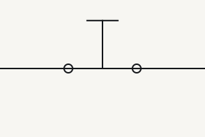
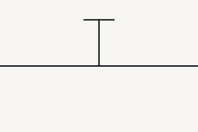
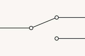
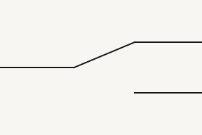
    Fig. 6 — Switch (SPDT), switch (DPDT) and relay (coil and SPDT contact), the mark that tells them apart ringedSwitch (SPDT), switch (DPDT) and relay (coil and SPDT contact), the mark that tells them apart ringed

Poles and throws

Single throwDouble throw
Single pole
SPST switch symbol, US style, single pole, single throw: 2 contact terminals

SPST

2 contact terminals

SPDT switch symbol, US style, single pole, double throw: 3 contact terminals

SPDT

3 contact terminals

Double pole
DPST switch symbol, US style, double pole, single throw: 4 contact terminals

DPST

4 contact terminals

DPDT switch symbol, US style, double pole, double throw: 6 contact terminals

DPDT

6 contact terminals

Each pole has a common terminal plus one terminal for each throw. So an SPST switch has 2 contact terminals, SPDT 3, DPST 4 and DPDT 6.⁠Source 1Source 3

Single throwDouble throw
Single pole
SPST switch symbol, IEC style, single pole, single throw: 2 contact terminals

SPST

2 contact terminals

SPDT switch symbol, IEC style, single pole, double throw: 3 contact terminals

SPDT

3 contact terminals

Double pole
DPST switch symbol, IEC style, double pole, single throw: 4 contact terminals

DPST

4 contact terminals

DPDT switch symbol, IEC style, double pole, double throw: 6 contact terminals

DPDT

6 contact terminals

Each pole has a common terminal plus one terminal for each throw. So an SPST switch has 2 contact terminals, SPDT 3, DPST 4 and DPDT 6.⁠Source 1Source 3

Fig. 7 — SPST, SPDT, DPST and DPDT switch symbols, US style, set out by poles and throwsSPST, SPDT, DPST and DPDT switch symbols, IEC style, set out by poles and throws ⁠Source 1Source 6

Notes

A cross on the contact marks a circuit breaker

In the cross-qualified breaker convention shown here, the cross belongs to the fixed-contact conductor and identifies a circuit breaker. It does not show whether the breaker is presently tripped.⁠Source 8 The legend draws the circuit breaker beside the fuse, on a contact like the switch on this sheet.

DPST works like two on-off switches linked together

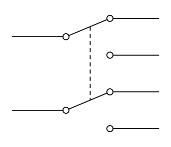
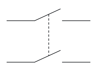
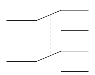
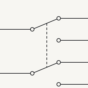
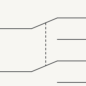
A double-pole, single-throw (DPST) switch has two moving poles worked by one mechanism, each closing onto its own fixed contact. It acts like two SPST switches linked together.⁠Source 1 The DPDT switch on this sheet links two changeover arms the same way, with a dashed line that carries no current. Each arm’s own terminal is the common terminal, so counting the poles and throws tells you how many contact terminals to expect.

Break-before-make leaves one contact before touching the next

As a multi-position switch moves, a break-before-make contact leaves one position before it touches the next. A make-before-break contact briefly bridges the two positions instead.⁠Source 9 The relay symbol uses the same contact names and adds the Form A, B and C labels.

Pick an answer to see the reason.

  1. Question 1

    Count the moving arms and the contacts each one can reach. What kind of switch is this?

    Two identical sections, one above the other. In each, a lead from the left ends in a hinged arm that rests against the upper of two contacts on the right, and each contact has its own lead going right. A dashed line joins the two arms.

    Two identical sections, one above the other. In each, a lead from the left ends in a hinged arm that rests against the upper of two contacts on the right, and each contact has its own lead going right. A dashed line joins the two arms.

    Not this one Right Answer

    The answer is “DPDT”. Count the arms and look for a coil: an SPDT switch has one arm between two fixed contacts, a DPDT switch has two arms tied by a dashed link, and a relay adds a coil linked to its contacts.A double-pole, single-throw (DPST) switch has two moving poles worked by one mechanism, each closing onto its own fixed contact. It acts like two SPST switches linked together.A dashed line joining parts of a symbol shows a mechanical link: the parts move together, but the line is not a wire and carries no current. A double-pole, double-throw (DPDT) switch works like two SPDT switches ganged together. The dashed line between its two arms is a mechanical link: the arms move together, but no current passes along it.

  2. Question 2

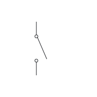
    How many throws does this switch have?

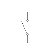
    A lead comes down from the top and ends in a hinged arm that swings clear of a single contact below it. That contact's lead carries on down.

    A lead comes down from the top and ends in a hinged arm that swings clear of a single contact below it. That contact's lead carries on down.

    Not this one Right Answer

    The answer is “One: the contact the arm closes onto”. Poles count the separate circuits a switch controls; throws count the contact destinations available to each pole. An off position is not an additional throw.Poles count the separate circuits a switch controls; throws count the contact destinations available to each pole. An off position is not an additional throw. In a switch symbol the moving arm is the pole, and each fixed contact it can close onto is a throw.

  3. Question 3

    Is this push button normally open or normally closed?

    A horizontal bar resting across two contacts, one with a lead to the left and one with a lead to the right. A short vertical stem rises from the middle of the bar to a small cap.

    A horizontal bar resting across two contacts, one with a lead to the left and one with a lead to the right. A short vertical stem rises from the middle of the bar to a small cap.

    Not this one Right Answer

    The answer is “Normally closed”. Switch contacts are drawn in their normal status: the position they rest in with no force applied. A normally-open (NO) contact is drawn open and a normally-closed (NC) contact closed; for a momentary push button, normal means not pressed.The momentary-switch model has two settled states: released, with the contacts in their drawn normal status, and pressed, with each contact in the opposite state. It leaves out contact bounce, contact resistance and latching. The two push buttons differ only in the resting position drawn: the normally-open bar is drawn clear of its contacts and the normally-closed bar touching them. Pressing reverses each one; the drawing does not change.

  4. Question 4

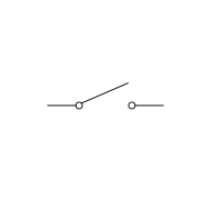
    This switch is set to the position it is drawn in. Under the ideal-contact model, is there a conducting path between its two terminals?

    12

    A lead from the left, labelled 1, ends in a hinged arm that is lifted clear of the contact on the right, whose lead is labelled 2.

    12

    A lead from the left, labelled 1, ends in a hinged arm that is lifted clear of the contact on the right, whose lead is labelled 2.

    Not this one Right Answer

    The answer is “No: the arm is lifted clear”. The ideal-contact model treats an open contact as electrically isolating, so no current passes, and a closed contact as making its two terminals electrically common, with no voltage between them. It leaves out contact bounce and contact resistance.The ideal-contact model treats an open contact as electrically isolating, so no current passes, and a closed contact as making its two terminals electrically common, with no voltage between them. It leaves out contact bounce and contact resistance. Under the ideal-contact model, an open switch breaks the conducting path between its two terminals.

  5. Question 5

    What happens when you let go of this push button?

    12

    A horizontal bar held above two contacts without touching them, one contact with a lead to the left, labelled 1, and one with a lead to the right, labelled 2. A short stem topped by a small cap rises from the middle of the bar.

    12

    A horizontal bar held above two contacts without touching them, one contact with a lead to the left, labelled 1, and one with a lead to the right, labelled 2. A short stem topped by a small cap rises from the middle of the bar.

    Not this one Right Answer

    The answer is “It returns to the position it is drawn in”. A momentary switch has an internal spring that returns it to its resting position as soon as it is released. A switch without that spring, such as a knife switch or most toggle switches, stays wherever it was last put.The two push buttons differ only in the resting position drawn: the normally-open bar is drawn clear of its contacts and the normally-closed bar touching them. Pressing reverses each one; the drawing does not change. The momentary push buttons shown here change contact state while pressed and return to their drawn, unactuated state when released.

Answer key

  1. 1

    DPDT

  2. 2

    One: the contact the arm closes onto

  3. 3

    Normally closed

  4. 4

    No: the arm is lifted clear

    12
    12
  5. 5

    It returns to the position it is drawn in

Questions

What is the difference between SPDT and DPDT?
SPDT has one moving arm that connects its common terminal to either of two contacts. DPDT is two of those arms moved together, shown by a dashed link that carries no current.⁠Source 1Source 6
What does momentary mean on a switch?
A spring returns a momentary switch to its resting position as soon as you let go, as the push buttons here do. A switch without that spring stays wherever it was last put.⁠Source 1Source 10
What do I and O on a power switch mean?
They are IEC 60417 equipment marks for power on (5007) and off (5008), printed on the product. A schematic switch symbol draws the contacts instead.⁠Source 11

Print and files

Sources

12 sources, numbered as cited
  1. ModEL — Electrical Switches, §§3.1–3.3 (pp. 16–19)

    Tony R. Kuphaldt, retrieved 2026-09-22.

  2. Design to Manufacturing Standards — Reference Designators (slide 33)

    Dieter Bergman, IPC, retrieved 2026-09-22. BT battery … CB circuit breaker … DS display, lamp, light emitting diode … RT thermistor

  3. ModEL — Electromechanical Relays, §§3.2–3.3 and §5.1 (normal and present contact status)

    Tony R. Kuphaldt, retrieved 2026-09-22.

  4. Lessons In Electric Circuits, Vol. V — §9, Circuit Schematic Symbols (pp. 130–139)

    Tony R. Kuphaldt, retrieved 2026-09-22.

  5. Electrical Schematics, §§1.3.1–1.3.5 — nodes, crossings, references and congruent drawings

    Tufts University, retrieved 2026-09-22.

  6. ModEL — Components and Symbols, §3.8 (switch symbols, poles, throws and dashed links, pp. 15–16)

    Tony R. Kuphaldt, retrieved 2026-09-23. Note the use of dashed lines to represent a mechanical connection between moving pieces of a component without implying an electrical connection between the same.

  7. ModEL — Components and Symbols, §3.11 (relay symbol, p. 21)

    Tony R. Kuphaldt, retrieved 2026-09-23. The schematic diagram symbol for a relay (shown on the left) is a combination of symbols – a solenoid shown mechanically linked to a switch.

  8. Circuit Breakers and Automatic Switches — breaker identification symbol (p. 10)

    Schneider Electric, retrieved 2026-09-22.

  9. ModEL — Electrical Switches, §3.4 (making and breaking order, p. 20)

    Tony R. Kuphaldt, retrieved 2026-09-23. it breaks contact with one pole before making contact with the next, giving it the name break-before-make

  10. ModEL — Electrical Switches, §§3.5.1–3.5.3 (toggle and pushbutton operators, p. 21)

    Tony R. Kuphaldt, retrieved 2026-09-23. Most toggle switches will come to rest in any of their lever positions, while others have an internal spring mechanism returning the lever to a certain normal position

  11. IEC 60417 — equipment-symbol overview: 5007, 5008 and 5009 (preview p. 6)

    International Electrotechnical Commission, retrieved 2026-09-22.

  12. ModEL — Components and Symbols, §3.20 (wire crossings and dashed links, p. 36)

    Tony R. Kuphaldt, retrieved 2026-09-23. use the new convention (dot) to show connections between wires, and the old convention (“loop”) to show wires crossing over each other without connection