Circuit Symbols
Drawing style

Battery symbol

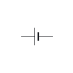
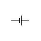
A battery symbol is a row of cells, each with its long line positive and its short line negative. In the drawings here a circle marks a generic source: + and − for DC, a sine wave for AC, an arrow for a current source.⁠Source 1Source 2

On this sheet

Symbol and terminals

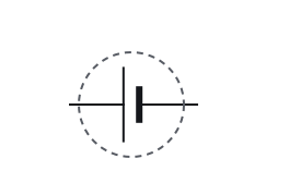
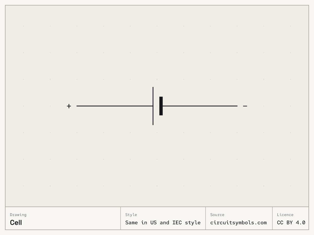
Fig. 1 — Cell, drawn the same in US and IEC style: long line is positive; terminals +, −

Terminals

⁠Source 1Source 3
+
The + mark identifies the higher-potential terminal relative to the − terminal. The polarity marks alone do not determine whether current is entering or leaving the source.
−
The − mark identifies the lower-potential terminal relative to the + terminal. It is not automatically the circuit's zero-volt reference.

Parts of the drawing
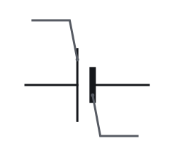
  • Cell symbol, with numbered leaders to the long thin line and the short thick line
1 Long thin line
2 Short thick line
In a cell symbol the long thin line is the positive terminal and the short thick line is the negative terminal.⁠Source 1
Fig. 2 — Cell symbol, its marks numbered
  • Cell symbol, turned 0°, with its terminal names attached

    0°

  • Cell symbol, turned 90°, with its terminal names attached

    90°

  • Cell symbol, turned 180°, with its terminal names attached

    180°

  • Cell symbol, turned 270°, with its terminal names attached

    270°

  • Cell symbol, mirrored, with its terminal names attached

    Mirrored

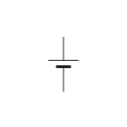
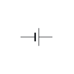
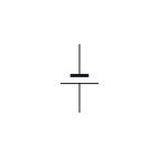
Rotating or mirroring a whole symbol, with its terminal identities and connections preserved, does not change the component. The terminal labels move with the drawing.⁠Source 4

Fig. 3 — Cell symbol at 0°, 90°, 180° and 270°, and mirrored

Variants

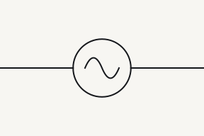
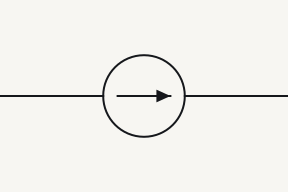
The three source circles are told apart by the mark inside: + and − signs for a DC voltage source, a sine wave for an AC voltage source and an arrow for a current source.⁠Source 1Source 2Source 5

  • +−

    Battery

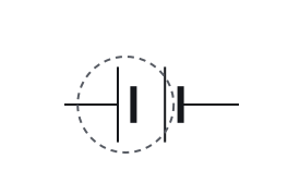
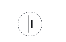
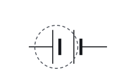
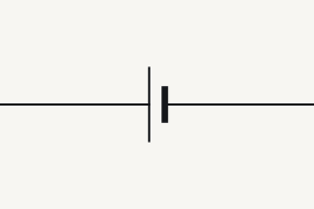
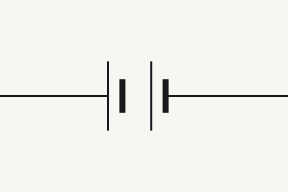
    A battery is drawn as several cells in a row; the terminals follow the same long-positive rule.⁠Source 1

  • +−

    DC voltage source

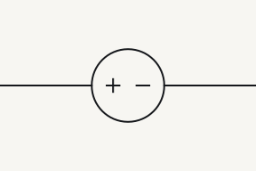
    The generic DC voltage-source drawing used in both views is a circle with + and − signs. An ideal voltage source fixes the voltage difference between those terminals.⁠Source 1

  • 12

    AC source

    The sinusoidal AC voltage-source drawing used here is a circle with a sine wave inside.⁠Source 2

    1, 2
    The sinusoidal AC voltage source shown here alternates its polarity between its two terminals; neither terminal is permanently positive.⁠Source 2Source 6
  • 12

    Current source

    The generic current-source drawing used in both views is a circle with an arrow giving conventional current direction. An ideal current source fixes that current; the arrow does not give voltage polarity.⁠Source 1

    1
    Conventional current enters the ideal current source at the tail end of its arrow; this does not specify that terminal's voltage polarity.⁠Source 1
    2
    Conventional current leaves the ideal current source at the arrowhead end; this does not specify that terminal's voltage polarity.⁠Source 1

Telling them apart

  • A cell is one long-and-short pair of lines; a battery repeats the pair, drawn as several cells in a row. Both follow the same rule: the long line is positive.⁠Source 1Source 5

Often confused with

    • Cell symbol; ringed: lines differ in length

      Cell

      Lines differ in length

    • Battery symbol; ringed: lines differ in length

      Battery

      Lines differ in length

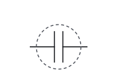
    • Capacitor symbol; ringed: two plates drawn the same length

      Capacitor

      Two plates drawn the same length

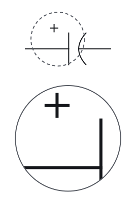
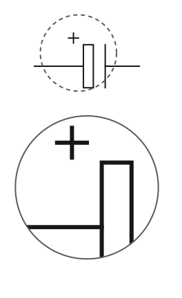
    • Polarised capacitor symbol in US style; ringed: polarity mark, with the ringed part enlarged 3:1 in a detail view

      Polarised capacitor

      Polarity mark

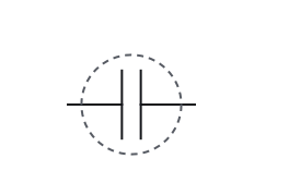
    A cell and a capacitor are both drawn as two parallel lines. In a cell, and in each cell of a battery, the lines differ in length and the long line is the positive terminal; a capacitor's two plates are drawn the same length, and only a polarised capacitor adds a polarity mark.⁠Source 1Source 2Source 5Source 7

    • Cell symbol; ringed: lines differ in length

      Cell

      Lines differ in length

    • Battery symbol; ringed: lines differ in length

      Battery

      Lines differ in length

    • Capacitor symbol; ringed: two plates drawn the same length

      Capacitor

      Two plates drawn the same length

    • Polarised capacitor symbol in IEC style; ringed: polarity mark, with the ringed part enlarged 3:1 in a detail view

      Polarised capacitor

      Polarity mark

    A cell and a capacitor are both drawn as two parallel lines. In a cell, and in each cell of a battery, the lines differ in length and the long line is the positive terminal; a capacitor's two plates are drawn the same length, and only a polarised capacitor adds a polarity mark.⁠Source 1Source 2Source 5Source 7

    Fig. 4 — Cell, battery, capacitor and polarised capacitor, the mark that tells them apart ringedCell, battery, capacitor and polarised capacitor, the mark that tells them apart ringed

Notes

A circle with V, A, M or a cross is not a source

Several symbols are circles told apart by what is inside: V for a voltmeter, A for an ammeter, a cross for a lamp and M for a motor.⁠Source 8Source 9Source 10 The textbooks cited here draw a generator as a circle marked Gen, with its two terminals on opposite sides. A generator converts mechanical energy, from a turning shaft, into electrical energy.⁠Source 2Source 11 So read the mark inside a circle before calling it a source; the circuit symbols chart draws the meters, the lamp and the motor side by side.

In the IPC list a battery is BT

In the IPC reference-designator list cited here, BT is a battery, CB a circuit breaker, DS a lamp, display or light-emitting diode, and RT a thermistor. Other naming systems use other letters.⁠Source 12 So a parts list may call a battery BT1 where a resistor is R1. The reference designator letters are covered on how to read a schematic.

Pick an answer to see the reason.

  1. Question 1

    This cell has been turned round and its labels hidden. Which line is its positive terminal?

    Two horizontal lines, one above the other: the lower line is long and thin, the upper line short and thick. A lead goes up from the upper line and down from the lower one.

    Not this one Right Answer

    The answer is “The longer, thinner line”. Rotating or mirroring a whole symbol, with its terminal identities and connections preserved, does not change the component. The terminal labels move with the drawing.A cell and a capacitor are both drawn as two parallel lines. In a cell, and in each cell of a battery, the lines differ in length and the long line is the positive terminal; a capacitor's two plates are drawn the same length, and only a polarised capacitor adds a polarity mark. In a cell symbol the long thin line is the positive terminal and the short thick line is the negative terminal.

  2. Question 2

    What does this drawing stand for?

    Two pairs of vertical lines in a row, each pair a long thin line and a short thick line, with a lead out to the left and a lead out to the right.

    Not this one Right Answer

    The answer is “A battery of several cells”. A cell is one long-and-short pair of lines; a battery repeats the pair, drawn as several cells in a row. Both follow the same rule: the long line is positive.A cell and a capacitor are both drawn as two parallel lines. In a cell, and in each cell of a battery, the lines differ in length and the long line is the positive terminal; a capacitor's two plates are drawn the same length, and only a polarised capacitor adds a polarity mark. A battery is drawn as several cells in a row; the terminals follow the same long-positive rule.

  3. Question 3

    Which source does this circle stand for?

    12

    A circle with a single sine wave inside and a lead out to each side, labelled 1 on the left and 2 on the right.

    Not this one Right Answer

    The answer is “An AC voltage source”. The three source circles are told apart by the mark inside: + and − signs for a DC voltage source, a sine wave for an AC voltage source and an arrow for a current source.The generic current-source drawing used in both views is a circle with an arrow giving conventional current direction. An ideal current source fixes that current; the arrow does not give voltage polarity. The sinusoidal AC voltage-source drawing used here is a circle with a sine wave inside.

  4. Question 4

    What does the arrow inside this source circle tell you?

    12

    A circle with an arrow inside pointing from left to right, and a lead out to each side, labelled 1 on the left and 2 on the right.

    Not this one Right Answer

    The answer is “The direction of the current through the source”. A diagonal arrow through a symbol marks it as adjustable, whatever the component, so the body under the arrow says what it is: plates for a variable capacitor, a zigzag or rectangle for a variable resistor, a coil for a variable inductor.Conventional current leaves the ideal current source at the arrowhead end; this does not specify that terminal's voltage polarity. The generic current-source drawing used in both views is a circle with an arrow giving conventional current direction. An ideal current source fixes that current; the arrow does not give voltage polarity.

  5. Question 5

    The labels on this source are hidden. Which terminal is at the higher potential?

    A circle with a lead out to each side. Inside the circle, a plus sign sits toward the right-hand lead and a minus sign toward the left-hand lead.

    Not this one Right Answer

    The answer is “The one beside the + sign”. Rotating or mirroring a whole symbol, with its terminal identities and connections preserved, does not change the component. The terminal labels move with the drawing.The sinusoidal AC voltage source shown here alternates its polarity between its two terminals; neither terminal is permanently positive. The + mark identifies the higher-potential terminal relative to the − terminal. The polarity marks alone do not determine whether current is entering or leaving the source.

Answer key

  1. 1

    The longer, thinner line

  2. 2

    A battery of several cells

  3. 3

    An AC voltage source

  4. 4

    The direction of the current through the source

  5. 5

    The one beside the + sign

Questions

Which line in a battery symbol is positive?
The longer line. It stays the positive terminal however the symbol is turned, because the drawing rotates with its terminals.⁠Source 1Source 4
What is the difference between a cell and a battery symbol?
A cell is one long-and-short pair of lines. A battery repeats the pair, drawn as several cells in a row, and the long line is still positive.⁠Source 1
What does the arrow in a current source mean?
It gives the direction of conventional current through the source. It does not say which terminal is at the higher voltage.⁠Source 1
What is the DC power supply symbol?
A circle with + and − inside marks a generic DC voltage source. A battery supply is drawn with the cell or battery symbol instead.⁠Source 1

Print and files

Printable symbol sheetPrintable symbol sheet More worksheets

Variants as SVG line art: Battery, DC voltage source, AC source, Current source
Free to reuse under CC BY 4.0. Credit: Circuit Symbols (circuitsymbols.com). Licence and credit

Sources

12 sources, numbered as cited
  1. ModEL — Components and Symbols, §3.5 (cells and ideal source symbols, p. 12)

    Tony R. Kuphaldt, retrieved 2026-09-22.

  2. Lessons In Electric Circuits, Vol. V — §9, Circuit Schematic Symbols (pp. 130–139)

    Tony R. Kuphaldt, retrieved 2026-09-22.

  3. ModEL — Sources and Loads, Voltmeters and Ammeters, §§4.2–4.6 and §6.2

    Tony R. Kuphaldt, retrieved 2026-09-22.

  4. Electrical Schematics, §§1.3.1–1.3.5 — nodes, crossings, references and congruent drawings

    Tufts University, retrieved 2026-09-22.

  5. DC Electrical Circuit Analysis — resistive devices and schematic ground symbols (pp. 53, 59–64)

    James M. Fiore, Mohawk Valley Community College, retrieved 2026-09-22.

  6. ModEL — Components and Symbols, §§3.13–3.14 (inductors and transformers, pp. 24–26)

    Tony R. Kuphaldt, retrieved 2026-09-22.

  7. ModEL — Components and Symbols, §3.15 (capacitor polarity, pp. 27–28)

    Tony R. Kuphaldt, retrieved 2026-09-22.

  8. ModEL — Components and Symbols, §§3.2–3.3 (meters in series and parallel, pp. 8–11)

    Tony R. Kuphaldt, retrieved 2026-09-22.

  9. ModEL — Electrical Switches, §§3.1–3.3 (pp. 16–19)

    Tony R. Kuphaldt, retrieved 2026-09-22.

  10. Combined Science: Synergy, June 2022 paper — motor symbol (p. 47)

    AQA, retrieved 2026-09-22.

  11. ModEL — Components and Symbols, §3.12 (electromagnetic generator symbol, p. 23)

    Tony R. Kuphaldt, retrieved 2026-09-23. Generators transform mechanical energy into electrical energy.

  12. Design to Manufacturing Standards — Reference Designators (slide 33)

    Dieter Bergman, IPC, retrieved 2026-09-22. BT battery … CB circuit breaker … DS display, lamp, light emitting diode … RT thermistor