Circuit Symbols
Drawing style

Resistor symbol

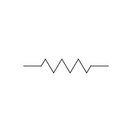
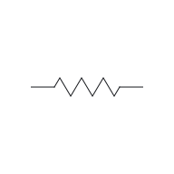
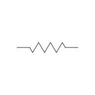
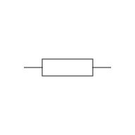
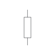
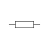
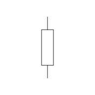
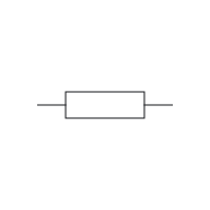
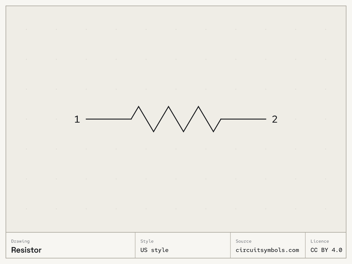
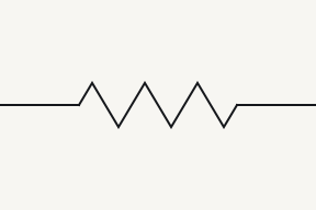
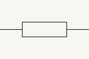
In the drawings here a resistor is a zigzag (US style) or a plain rectangle (IEC style): one part, labelled R, with interchangeable ends. An arrow through the body marks a variable resistor; one that stops on it is a potentiometer’s wiper.⁠Source 1Source 2Source 3Source 4

Reference Designator R⁠Source 3

On this sheet

Symbol and terminals

US style

IEC style

Fig. 1 — Resistor, US zigzag and IEC rectangle; terminals 1, 2

Terminals

12
A fixed resistor has two interchangeable terminals; the symbol has no polarity.⁠Source 1

Parts of the drawing

  • Resistor symbol in US style, with numbered leaders to the zigzag

    US style

  • Resistor symbol in IEC style, with numbered leaders to the rectangle

    IEC style

1 Zigzag
2 Rectangle
A resistor symbol stands for a component that opposes current. The zigzag (US style) and the plain rectangle (IEC style) are two drawings of the same component.⁠Source 1Source 2
Fig. 2 — Resistor symbol in US style and IEC style, its marks numbered
  • Resistor symbol, US style, turned 0°, with its terminal names attached

    0°

  • Resistor symbol, US style, turned 90°, with its terminal names attached

    90°

  • Resistor symbol, US style, turned 180°, with its terminal names attached

    180°

  • Resistor symbol, US style, turned 270°, with its terminal names attached

    270°

  • Resistor symbol, US style, mirrored, with its terminal names attached

    Mirrored

Rotating or mirroring a whole symbol, with its terminal identities and connections preserved, does not change the component. The terminal labels move with the drawing.⁠Source 5

  • Resistor symbol, IEC style, turned 0°, with its terminal names attached

    0°

  • Resistor symbol, IEC style, turned 90°, with its terminal names attached

    90°

  • Resistor symbol, IEC style, turned 180°, with its terminal names attached

    180°

  • Resistor symbol, IEC style, turned 270°, with its terminal names attached

    270°

  • Resistor symbol, IEC style, mirrored, with its terminal names attached

    Mirrored

Rotating or mirroring a whole symbol, with its terminal identities and connections preserved, does not change the component. The terminal labels move with the drawing.⁠Source 5

Fig. 3 — Resistor symbol, US style at 0°, 90°, 180° and 270°, and mirroredResistor symbol, IEC style at 0°, 90°, 180° and 270°, and mirrored

Variants

  • 12
    12

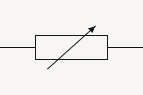
    Variable resistor

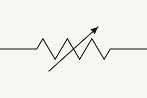
    A diagonal arrow through the resistor body marks a variable resistor.⁠Source 4

    1, 2
    This symbol has two terminals and no polarity mark. The labels 1 and 2 only tell the two ends apart.⁠Source 4Source 6Source 7
  • 1W2
    1W2

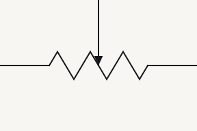
    Potentiometer

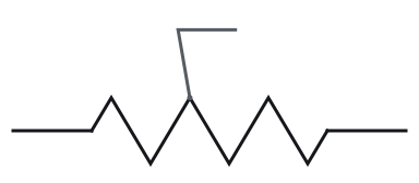
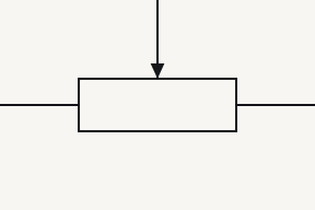
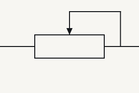
    A potentiometer has three terminals: the two ends of the resistive track and a wiper, drawn as an arrow touching the body.⁠Source 1

    1, 2
    Terminals 1 and 2 are the fixed terminals, one at each end of the resistive track.⁠Source 1
    W
    W is the wiper: the movable third terminal, drawn as the arrow touching the body. It makes contact wherever it rests along the track.⁠Source 1
  • 12
    12

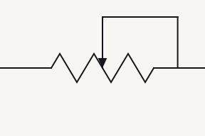
    Rheostat

    A rheostat is a variable resistor used with two terminals: one end of the track and the wiper.⁠Source 1

  • 12
    12

    Thermistor

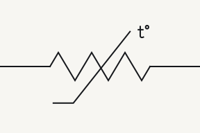
    A thermistor's resistance changes with temperature. NTC resistance falls as temperature rises; PTC resistance rises. A generic thermistor symbol without a type label does not distinguish the two.⁠Source 2Source 8

  • 12
    12

    LDR (light-dependent resistor)
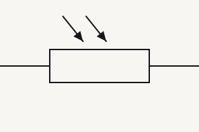
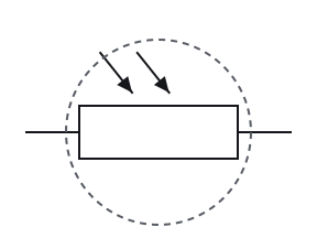
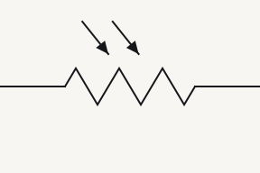
    Two arrows arriving at a resistor body mark a light-dependent resistor (photoresistor).⁠Source 4

Telling them apart

  • An arrow drawn right through a resistor body marks a variable resistor with two terminals. An arrow that stops on the body is a wiper, the movable third terminal of a potentiometer.⁠Source 1Source 4
  • A rheostat uses only two terminals, one end of the track and the wiper, where a potentiometer brings out all three: both track ends and the wiper.⁠Source 1
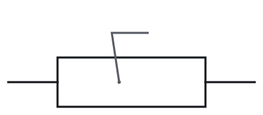
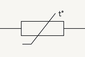
  • The textbooks cited here mark a thermistor in two ways: a line through the body that ends in a short flat foot rather than an arrowhead, or the letters t° beside the body. Either marks a resistance that changes with temperature; neither says whether it is NTC or PTC.⁠Source 2Source 4

Often confused with

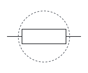
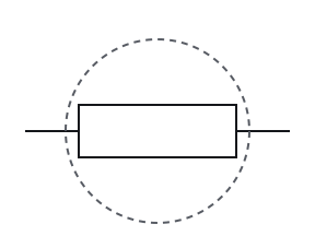
    • Resistor symbol in IEC style; ringed: plain rectangle

      Resistor

      Plain rectangle

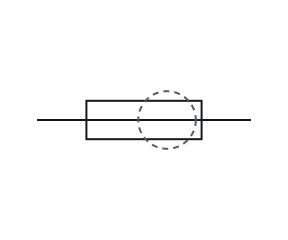
    • Fuse symbol in IEC style; ringed: A line running through it

      Fuse

      A line running through it

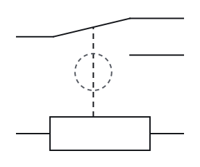
    • Relay (coil and SPDT contact) symbol in IEC style; ringed: dashed line to a contact

      Relay (coil and SPDT contact)

      Dashed line to a contact

    Three IEC symbols are rectangles: a plain rectangle is a resistor, a rectangle with a line running through it end to end is a fuse, and a rectangle joined by a dashed line to a contact is a relay coil.⁠Source 6Source 9Source 10

    Fig. 4 — Resistor, fuse and relay (coil and SPDT contact), the mark that tells them apart ringed
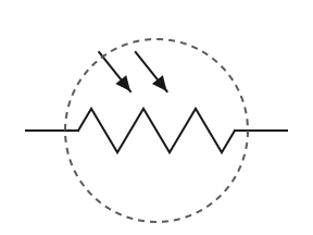
    • Light-dependent resistor symbol in US style; ringed: A resistor body

      Light-dependent resistor

      A resistor body

    • Photodiode symbol; ringed: A diode's triangle and bar

      Photodiode

      A diode's triangle and bar

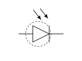
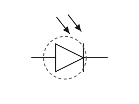
    An LDR and a photodiode both have arrows arriving at the body, so the body decides: a resistor body for an LDR, a diode's triangle and bar for a photodiode.⁠Source 2Source 4

    • Light-dependent resistor symbol in IEC style; ringed: A resistor body

      Light-dependent resistor

      A resistor body

    • Photodiode symbol; ringed: A diode's triangle and bar

      Photodiode

      A diode's triangle and bar

    An LDR and a photodiode both have arrows arriving at the body, so the body decides: a resistor body for an LDR, a diode's triangle and bar for a photodiode.⁠Source 2Source 4

    Fig. 5 — Light-dependent resistor and photodiode, the mark that tells them apart ringedLight-dependent resistor and photodiode, the mark that tells them apart ringed
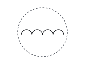
    • Inductor symbol in US style; ringed: loops

      Inductor

      Loops

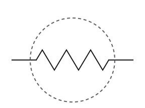
    • Resistor symbol in US style; ringed: zigzag

      Resistor

      Zigzag

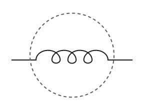
    An inductor is drawn as a coil, a row of loops or humps for its turns. A resistor has no turns: it is a zigzag in US drawings and a plain rectangle in IEC drawings.⁠Source 2Source 4

    • Inductor symbol in IEC style; ringed: humps

      Inductor

      Humps

    • Resistor symbol in IEC style; ringed: plain rectangle

      Resistor

      Plain rectangle

    An inductor is drawn as a coil, a row of loops or humps for its turns. A resistor has no turns: it is a zigzag in US drawings and a plain rectangle in IEC drawings.⁠Source 2Source 4

    Fig. 6 — Inductor and resistor, the mark that tells them apart ringedInductor and resistor, the mark that tells them apart ringed

Notes

An arrow through any symbol means adjustable

A diagonal arrow through a symbol marks it as adjustable, whatever the component, so the body under the arrow says what it is: plates for a variable capacitor, a zigzag or rectangle for a variable resistor, a coil for a variable inductor.⁠Source 2Source 4 Here that is the variable resistor; the capacitor symbol page draws the same arrow through a pair of plates.

4k7 means 4.7 kΩ: the letter sits where the decimal point would

Values printed beside a symbol may put the multiplier letter where the decimal point would be: 4k7 means 4.7 kΩ, 3R9 means 3.9 Ω, 47R means 47 Ω and 2M2 means 2.2 MΩ. IEC 60062 sets out this letter code.⁠Source 2Source 11Source 12 Capacitor values follow the same letter code with p and n, as the capacitor symbol page shows. The designator printed beside a value, such as R1, is covered on how to read a schematic.

Pick an answer to see the reason.

  1. Question 1

    Which drawing style shows a resistor like this?

    12

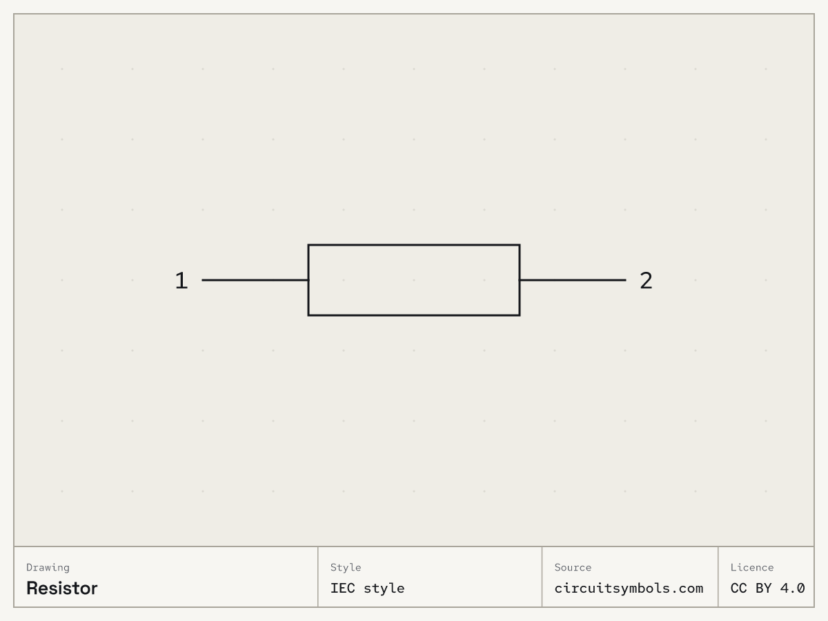
    A plain rectangle with a lead out to each side, labelled 1 on the left and 2 on the right.

    Not this one Right Answer

    The answer is “IEC style”. US style names the American drawing convention used here, including the resistor zigzag. IEEE 315-1975 (ANSI Y32.2) is a historical reference; IEEE lists it as inactive-reserved, with inactivation dated 7 November 2019.Three IEC symbols are rectangles: a plain rectangle is a resistor, a rectangle with a line running through it end to end is a fuse, and a rectangle joined by a dashed line to a contact is a relay coil. A resistor symbol stands for a component that opposes current. The zigzag (US style) and the plain rectangle (IEC style) are two drawings of the same component.

  2. Question 2

    What does this drawing show?

    12

    A zigzag line with a lead out to each side, labelled 1 and 2, and a diagonal arrow drawn right through it.

    Not this one Right Answer

    The answer is “A variable resistor”. An arrow drawn right through a resistor body marks a variable resistor with two terminals. An arrow that stops on the body is a wiper, the movable third terminal of a potentiometer.The textbooks cited here mark a thermistor in two ways: a line through the body that ends in a short flat foot rather than an arrowhead, or the letters t° beside the body. Either marks a resistance that changes with temperature; neither says whether it is NTC or PTC. A diagonal arrow through the resistor body marks a variable resistor.

  3. Question 3

    This resistor is drawn upright instead of across the page. Which terminal is positive now?

    12

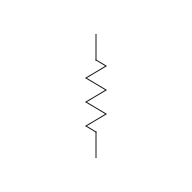
    A zigzag line drawn upright, with a lead going up, labelled 1, and a lead going down, labelled 2.

    Not this one Right Answer

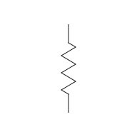
    The answer is “Neither: a fixed resistor has no polarity”. This symbol has two terminals and no polarity mark. The labels 1 and 2 only tell the two ends apart.Rotating or mirroring a whole symbol, with its terminal identities and connections preserved, does not change the component. The terminal labels move with the drawing. A fixed resistor has two interchangeable terminals; the symbol has no polarity.

  4. Question 4

    Its labels are hidden. What is this part?

    A plain rectangle with a lead out to each side, and a third lead coming down from above that ends in an arrowhead touching the top of the rectangle.

    Not this one Right Answer

    The answer is “A potentiometer”. A rheostat uses only two terminals, one end of the track and the wiper, where a potentiometer brings out all three: both track ends and the wiper.An arrow drawn right through a resistor body marks a variable resistor with two terminals. An arrow that stops on the body is a wiper, the movable third terminal of a potentiometer.Two arrows arriving at a resistor body mark a light-dependent resistor (photoresistor). A potentiometer has three terminals: the two ends of the resistive track and a wiper, drawn as an arrow touching the body.

  5. Question 5

    A thermistor is drawn with no other marking beside it. Does its resistance rise or fall as it warms?

    12

    A plain rectangle with a lead out to each side, labelled 1 and 2. A line runs diagonally up through it from a short flat foot at the lower left, and the letters t° sit beside its upper end.

    Not this one Right Answer

    The answer is “You cannot tell from the symbol alone”. The textbooks cited here mark a thermistor in two ways: a line through the body that ends in a short flat foot rather than an arrowhead, or the letters t° beside the body. Either marks a resistance that changes with temperature; neither says whether it is NTC or PTC.The textbooks cited here mark a thermistor in two ways: a line through the body that ends in a short flat foot rather than an arrowhead, or the letters t° beside the body. Either marks a resistance that changes with temperature; neither says whether it is NTC or PTC. A thermistor's resistance changes with temperature. NTC resistance falls as temperature rises; PTC resistance rises. A generic thermistor symbol without a type label does not distinguish the two.

Answer key

  1. 1

    IEC style

  2. 2

    A variable resistor

  3. 3

    Neither: a fixed resistor has no polarity

  4. 4

    A potentiometer

  5. 5

    You cannot tell from the symbol alone

Questions

Why are there two resistor symbols?
They come from two drawing conventions. The zigzag is the US form and the rectangle the IEC form; both stand for the same resistor, with the same two terminals.⁠Source 1Source 2Source 9Source 13Source 14
What is the difference between a potentiometer and a rheostat?
A potentiometer brings out three terminals: both ends of the track and the wiper. A rheostat uses only two of them, one track end and the wiper, as a variable resistance.⁠Source 1
Does a thermistor symbol tell you NTC or PTC?
No. The t° letters or the line ending in a flat foot say the resistance changes with temperature, not which way. Look for NTC or PTC written beside the symbol.⁠Source 2Source 4Source 8

Print and files

Sources

14 sources, numbered as cited
  1. ModEL — Components and Symbols, §§3.6–3.7 (resistors and potentiometers, pp. 13–14)

    Tony R. Kuphaldt, retrieved 2026-09-22.

  2. DC Electrical Circuit Analysis — resistive devices and schematic ground symbols (pp. 53, 59–64)

    James M. Fiore, Mohawk Valley Community College, retrieved 2026-09-22.

  3. Design to Manufacturing Standards — Reference Designators (slide 33)

    Dieter Bergman, IPC, retrieved 2026-09-22. BT battery … CB circuit breaker … DS display, lamp, light emitting diode … RT thermistor

  4. Lessons In Electric Circuits, Vol. V — §9, Circuit Schematic Symbols (pp. 130–139)

    Tony R. Kuphaldt, retrieved 2026-09-22.

  5. Electrical Schematics, §§1.3.1–1.3.5 — nodes, crossings, references and congruent drawings

    Tufts University, retrieved 2026-09-22.

  6. ModEL — Components and Symbols, §3.10 (fuses and circuit breakers, p. 20)

    Tony R. Kuphaldt, retrieved 2026-09-22.

  7. ModEL — Components and Symbols, §3.11 (relay example with motor and lamp loads, p. 22)

    Tony R. Kuphaldt, retrieved 2026-09-23. the relay in turn controls the flow of electric current from two other sources, to two other loads

  8. Thermistors — NTC and PTC product-description definitions

    Murata Manufacturing, retrieved 2026-09-22.

  9. ModEL — Components and Symbols, §§3.4–3.6 (NEMA and IEC symbol families, pp. 11–13)

    Tony R. Kuphaldt, retrieved 2026-09-23. Two major divisions of symbology exist: the American NEMA (National Electrical Manufacturers Association) and the European IEC

  10. ModEL — Components and Symbols, §3.11 (relay symbol, p. 21)

    Tony R. Kuphaldt, retrieved 2026-09-23. The schematic diagram symbol for a relay (shown on the left) is a combination of symbols – a solenoid shown mechanically linked to a switch.

  11. ModEL — Ohm’s and Joule’s Laws, Resistor Ratings, and Electrical Safety, §6.2 (resistor labelling, p. 73)

    Tony R. Kuphaldt, retrieved 2026-09-23. a letter is used in place of a decimal point, the letter either being R (unit), K (kilo), M (mega), G (giga), T (tera), or L (milli). This is commonly referred to as the RKM code.

  12. IEC 60062:2016+AMD1:2019 — Marking codes for resistors and capacitors; public preview contents (preview p. 3)

    International Electrotechnical Commission, retrieved 2026-09-23. 4 Letter and numeral code for resistance and capacitance values … 4.2.1 The RKM code system … 4.3.1 The multiplier code system for capacitors

  13. IEEE 315-1975 — historical standard status

    IEEE Standards Association, retrieved 2026-09-22. Inactive-Reserved Standard

  14. IEC 60617:2026 DB — Graphical symbols for diagrams

    International Electrotechnical Commission, retrieved 2026-09-22.