Circuit Symbols
Drawing style

Inductor symbol

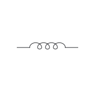
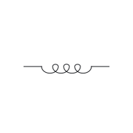
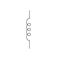
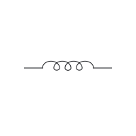
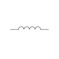
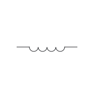
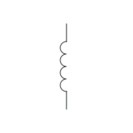
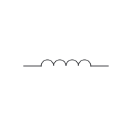
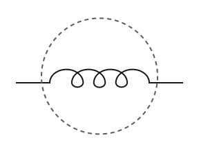
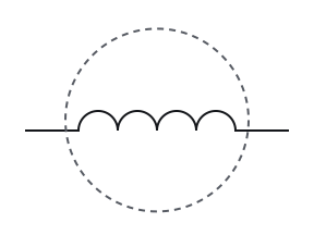
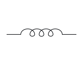
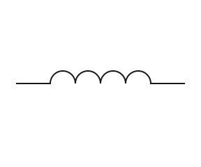
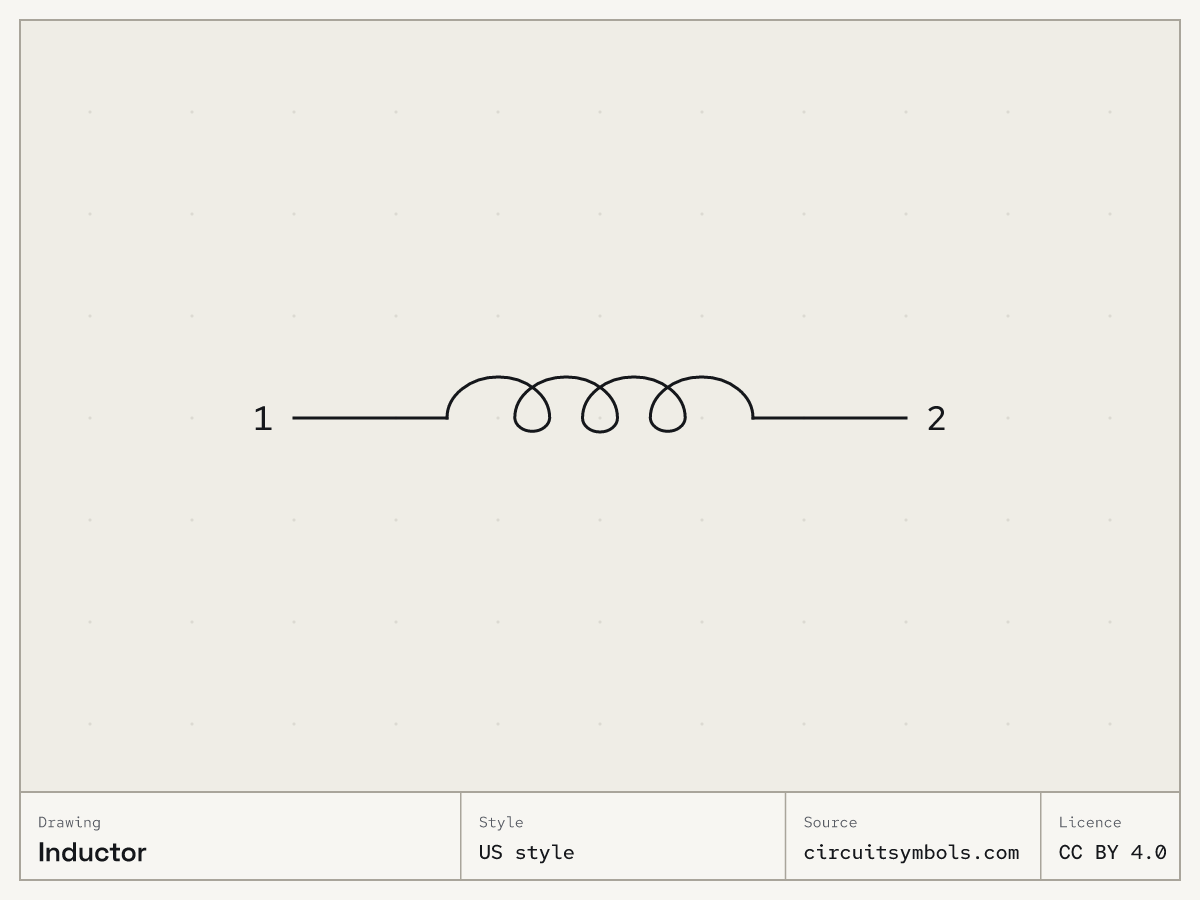
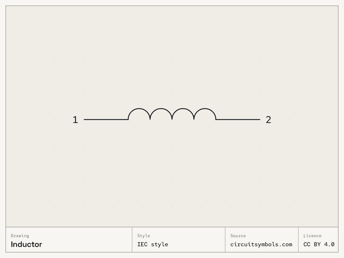
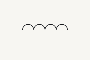
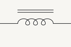
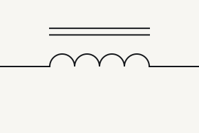
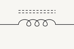
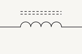
An inductor (L) is drawn as a coil: a row of loops in US style or humps in IEC style, two drawings of the same part. It stores energy in a magnetic field. In the drawings here, lines beside the coil mark its core.⁠Source 1Source 2Source 3Source 4

Reference Designator L⁠Source 2

On this sheet

Symbol and terminals

US style

IEC style

Fig. 1 — Inductor, US looped coil and IEC humps; terminals 1, 2

Terminals

12
The plain, uncoupled two-terminal inductor symbol has no fixed polarity mark; either terminal can be used as the voltage reference.⁠Source 1Source 3

Parts of the drawing

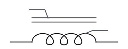
  • Iron-core inductor symbol in US style, with numbered leaders to the loops and the core lines
1 Core lines
In the coil convention used here, solid parallel core lines indicate iron and dashed core lines ferrite. The unmarked coil is used for air core. These drawings do not identify every material detail.⁠Source 1Source 4
2 Loops
Looped and semicircular coil drawings are alternative inductor forms. This sheet uses loops in its US view and humps in its IEC view; the winding and terminal roles are unchanged.⁠Source 1
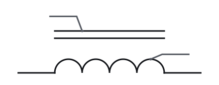
  • Iron-core inductor symbol in IEC style, with numbered leaders to the humps and the core lines
1 Core lines
In the coil convention used here, solid parallel core lines indicate iron and dashed core lines ferrite. The unmarked coil is used for air core. These drawings do not identify every material detail.⁠Source 1Source 4
2 Humps
Looped and semicircular coil drawings are alternative inductor forms. This sheet uses loops in its US view and humps in its IEC view; the winding and terminal roles are unchanged.⁠Source 1
Fig. 2 — Iron-core inductor symbol, US style, its marks numberedIron-core inductor symbol, IEC style, its marks numbered
  • Inductor symbol, US style, turned 0°, with its terminal names attached

    0°

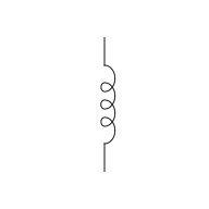
  • Inductor symbol, US style, turned 90°, with its terminal names attached

    90°

  • Inductor symbol, US style, turned 180°, with its terminal names attached

    180°

  • Inductor symbol, US style, turned 270°, with its terminal names attached

    270°

  • Inductor symbol, US style, mirrored, with its terminal names attached

    Mirrored

Rotating or mirroring a whole symbol, with its terminal identities and connections preserved, does not change the component. The terminal labels move with the drawing.⁠Source 5

  • Inductor symbol, IEC style, turned 0°, with its terminal names attached

    0°

  • Inductor symbol, IEC style, turned 90°, with its terminal names attached

    90°

  • Inductor symbol, IEC style, turned 180°, with its terminal names attached

    180°

  • Inductor symbol, IEC style, turned 270°, with its terminal names attached

    270°

  • Inductor symbol, IEC style, mirrored, with its terminal names attached

    Mirrored

Rotating or mirroring a whole symbol, with its terminal identities and connections preserved, does not change the component. The terminal labels move with the drawing.⁠Source 5

Fig. 3 — Inductor symbol, US style at 0°, 90°, 180° and 270°, and mirroredInductor symbol, IEC style at 0°, 90°, 180° and 270°, and mirrored

Variants

  • 12
    12
    Iron-core inductor
    12
    12
    Ferrite-core inductor

    Iron-core inductor and ferrite-core inductor

    As in Fig. 2, the parts of the drawing.

Often confused with

    • Inductor symbol in US style; ringed: loops

      Inductor

      Loops

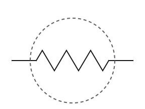
    • Resistor symbol in US style; ringed: zigzag

      Resistor

      Zigzag

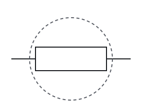
    An inductor is drawn as a coil, a row of loops or humps for its turns. A resistor has no turns: it is a zigzag in US drawings and a plain rectangle in IEC drawings.⁠Source 1Source 6

    • Inductor symbol in IEC style; ringed: humps

      Inductor

      Humps

    • Resistor symbol in IEC style; ringed: plain rectangle

      Resistor

      Plain rectangle

    An inductor is drawn as a coil, a row of loops or humps for its turns. A resistor has no turns: it is a zigzag in US drawings and a plain rectangle in IEC drawings.⁠Source 1Source 6

    Fig. 4 — Inductor and resistor, the mark that tells them apart ringedInductor and resistor, the mark that tells them apart ringed
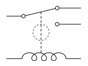
    • Relay (coil and SPDT contact) symbol in US style; ringed: dashed mechanical link

      Relay (coil and SPDT contact)

      Dashed mechanical link

    • Inductor symbol in US style

      Inductor

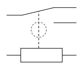
    A relay symbol combines a coil with the contacts it moves, joined by a dashed mechanical link. US drawings show the coil as loops and IEC drawings as a rectangle; a plain switch has no coil.⁠Source 7Source 8

    • Relay (coil and SPDT contact) symbol in IEC style; ringed: dashed mechanical link

      Relay (coil and SPDT contact)

      Dashed mechanical link

    • Inductor symbol in IEC style

      Inductor

    A relay symbol combines a coil with the contacts it moves, joined by a dashed mechanical link. US drawings show the coil as loops and IEC drawings as a rectangle; a plain switch has no coil.⁠Source 7Source 8

    Fig. 5 — Relay (coil and SPDT contact) and inductor, the mark that tells them apart ringedRelay (coil and SPDT contact) and inductor, the mark that tells them apart ringed

Where you meet it

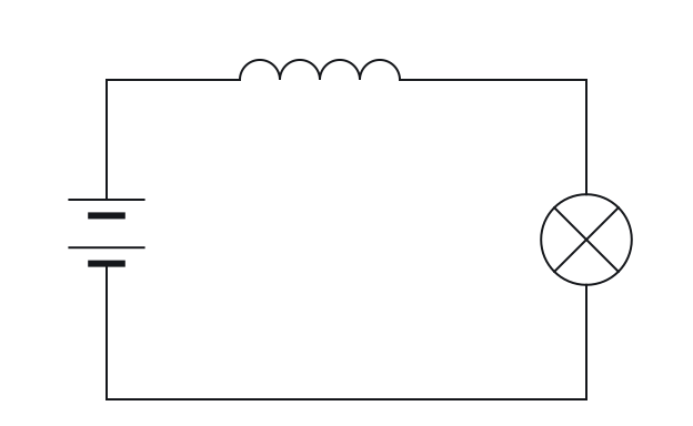
  • An inductor in a loop with a battery and a lamp, drawn with no values
  • An inductor in a loop with a battery and a lamp, drawn in IEC style with no values
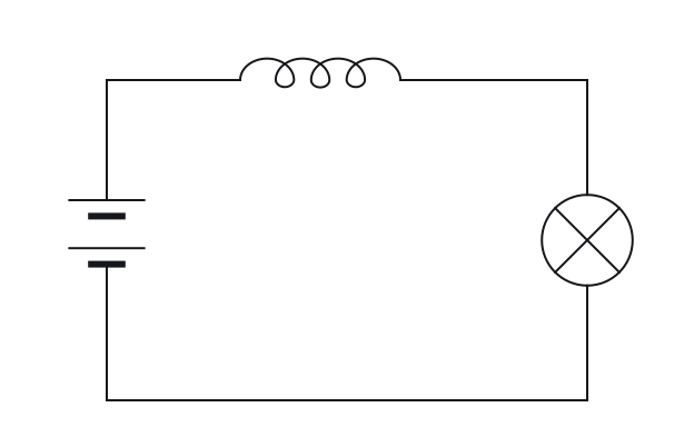
Fig. 6 — An inductor in a loop with a battery and a lamp; values left offAn inductor in a loop with a battery and a lamp; values left off ⁠Source 2

Notes

What is drawn with a coil decides what it is

A looped coil on its own can be an inductor, a solenoid or a relay coil, so what is drawn with it decides: a relay coil is joined to its contacts by a dashed link, and parallel lines beside a coil mark a magnetic core.⁠Source 7Source 9 A coil tied to contacts is read on the relay symbol page, and two windings facing each other make a transformer.

An extra lead is a tap; an arrow through the coil means variable

An extra lead joined partway along a coil marks a tapped inductor: the tap is a connection to part of the winding.⁠Source 1Source 10 A diagonal arrow through a coil marks a variable inductor.⁠Source 1 The centre-tapped transformer taps a winding the same way, and the variable resistor carries the same arrow.

Pick an answer to see the reason.

  1. Question 1

    This coil is drawn as a row of humps rather than loops. What has changed?

    12

    A row of humps with a lead out to each side, labelled 1 on the left and 2 on the right.

    Not this one Right Answer

    The answer is “Only the drawing style: it is still an inductor”. A transformer has two or more windings drawn facing each other, with core lines between them when it has a magnetic core. An inductor is a single winding with two terminals.In the coil convention used here, solid parallel core lines indicate iron and dashed core lines ferrite. The unmarked coil is used for air core. These drawings do not identify every material detail. Looped and semicircular coil drawings are alternative inductor forms. This sheet uses loops in its US view and humps in its IEC view; the winding and terminal roles are unchanged.

  2. Question 2

    Is this drawing an inductor?

    12

    A zigzag line with a lead out to each side, labelled 1 on the left and 2 on the right.

    Not this one Right Answer

    The answer is “No: a zigzag has no turns, so it is a resistor”. A resistor symbol stands for a component that opposes current. The zigzag (US style) and the plain rectangle (IEC style) are two drawings of the same component.Looped and semicircular coil drawings are alternative inductor forms. This sheet uses loops in its US view and humps in its IEC view; the winding and terminal roles are unchanged. An inductor is drawn as a coil, a row of loops or humps for its turns. A resistor has no turns: it is a zigzag in US drawings and a plain rectangle in IEC drawings.

  3. Question 3

    What do the two straight lines beside this coil mark?

    12

    A row of loops with a lead out to each side, labelled 1 and 2, and two straight lines drawn parallel to it.

    12

    A row of humps with a lead out to each side, labelled 1 and 2, and two straight lines drawn parallel to it.

    Not this one Right Answer

    The answer is “The coil's core”. A transformer has two or more windings drawn facing each other, with core lines between them when it has a magnetic core. An inductor is a single winding with two terminals.A capacitor symbol stands for two conductors separated by an insulator; the two parallel plates are a picture of that. In the coil convention used here, solid parallel core lines indicate iron and dashed core lines ferrite. The unmarked coil is used for air core. These drawings do not identify every material detail.

  4. Question 4

    Read the whole drawing. Which component is it?

    Upper part: a lead from the left ends in a hinged arm that rests against the upper of two contacts on the right, each contact with its own lead. Lower part: a row of loops between two leads. A dashed line runs from the top of the loops up to the arm.

    Upper part: a lead from the left ends in a hinged arm that rests against the upper of two contacts on the right, each contact with its own lead. Lower part: a rectangle between two leads. A dashed line runs from the top of the rectangle up to the arm.

    Not this one Right Answer

    The answer is “A relay”. A looped coil on its own can be an inductor, a solenoid or a relay coil, so what is drawn with it decides: a relay coil is joined to its contacts by a dashed link, and parallel lines beside a coil mark a magnetic core.A transformer has two or more windings drawn facing each other, with core lines between them when it has a magnetic core. An inductor is a single winding with two terminals. A relay symbol combines a coil with the contacts it moves, joined by a dashed mechanical link. US drawings show the coil as loops and IEC drawings as a rectangle; a plain switch has no coil.

  5. Question 5

    Which component does this drawing show?

    Two rows of loops facing each other, with two straight parallel lines between them and a dot near the top of each row. The left row's two leads go out to the left and the right row's two leads go out to the right.

    Two rows of humps facing each other, with two straight parallel lines between them and a dot near the top of each row. The left row's two leads go out to the left and the right row's two leads go out to the right.

    Not this one Right Answer

    The answer is “A transformer”. The separate-winding transformer shown here transfers energy magnetically between windings without an internal conducting connection between them. This description excludes an autotransformer, whose windings share a conducting connection.In the coil convention used here, solid parallel core lines indicate iron and dashed core lines ferrite. The unmarked coil is used for air core. These drawings do not identify every material detail. A transformer has two or more windings drawn facing each other, with core lines between them when it has a magnetic core. An inductor is a single winding with two terminals.

Answer key

  1. 1

    Only the drawing style: it is still an inductor

  2. 2

    No: a zigzag has no turns, so it is a resistor

  3. 3

    The coil's core

  4. 4

    A relay

  5. 5

    A transformer

Questions

What do the lines next to an inductor symbol mean?
They mark the core: solid lines for iron, dashed lines for ferrite, and no lines for an air core. Other drawings may define their own marks in a legend.⁠Source 1Source 4
Does an inductor have polarity?
A plain inductor does not: either terminal can serve as the reference. Dots appear only on coupled windings, such as a transformer's, where they mark matching polarity.⁠Source 1Source 3Source 10
Why is an inductor drawn as a coil?
Because the part is a coil of wire. The loops or humps picture its turns, which is also how you tell it from a resistor's zigzag or rectangle.⁠Source 1Source 3Source 6

Print and files

Sources

13 sources, numbered as cited
  1. Lessons In Electric Circuits, Vol. V — §9, Circuit Schematic Symbols (pp. 130–139)

    Tony R. Kuphaldt, retrieved 2026-09-22.

  2. Design to Manufacturing Standards — Reference Designators (slide 33)

    Dieter Bergman, IPC, retrieved 2026-09-22. BT battery … CB circuit breaker … DS display, lamp, light emitting diode … RT thermistor

  3. ModEL — Inductors and Inductive Circuits, §§3.1–3.2 (current change and polarity)

    Tony R. Kuphaldt, retrieved 2026-09-22.

  4. ECE 3310, Experiment 9 — inductor core symbols, Figure 2

    Wayne State University, retrieved 2026-09-22.

  5. Electrical Schematics, §§1.3.1–1.3.5 — nodes, crossings, references and congruent drawings

    Tufts University, retrieved 2026-09-22.

  6. DC Electrical Circuit Analysis — resistive devices and schematic ground symbols (pp. 53, 59–64)

    James M. Fiore, Mohawk Valley Community College, retrieved 2026-09-22.

  7. ModEL — Components and Symbols, §3.11 (relay symbol, p. 21)

    Tony R. Kuphaldt, retrieved 2026-09-23. The schematic diagram symbol for a relay (shown on the left) is a combination of symbols – a solenoid shown mechanically linked to a switch.

  8. ModEL — Components and Symbols, §3.8 (switch symbols, poles, throws and dashed links, pp. 15–16)

    Tony R. Kuphaldt, retrieved 2026-09-23. Note the use of dashed lines to represent a mechanical connection between moving pieces of a component without implying an electrical connection between the same.

  9. ModEL — Components and Symbols, §3.9 (solenoid coil symbols, p. 18)

    Tony R. Kuphaldt, retrieved 2026-09-23. The NEMA schematic diagram symbol for a coil is, not surprisingly, a series of loops resembling the coiled wire.

  10. ModEL — Transformers, §§4.1, 4.3–4.4 (windings, centre taps, autotransformers and dots)

    Tony R. Kuphaldt, retrieved 2026-09-22.

  11. ModEL — Components and Symbols, §§3.13–3.14 (inductors and transformers, pp. 24–26)

    Tony R. Kuphaldt, retrieved 2026-09-22.

  12. ModEL — Components and Symbols, §§3.6–3.7 (resistors and potentiometers, pp. 13–14)

    Tony R. Kuphaldt, retrieved 2026-09-22.

  13. ModEL — Components and Symbols, §3.15 (capacitor polarity, pp. 27–28)

    Tony R. Kuphaldt, retrieved 2026-09-22.