Circuit Symbols
Drawing style

Practice reading symbols

60 questions in 12 sets. Open a set, pick an answer and read the reason. Nothing is saved.

Mixed: across the legend

Mixed: across the legend

  1. Question 1

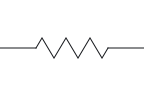
    Schematic A has this zigzag between two wires; schematic B has a plain rectangle in the same place. How are the two drawings related?

    12

    A zigzag line with a lead out to each side, labelled 1 on the left and 2 on the right.

    Not this one Right Answer

    The answer is “One resistor, drawn in two styles”. Three IEC symbols are rectangles: a plain rectangle is a resistor, a rectangle with a line running through it end to end is a fuse, and a rectangle joined by a dashed line to a contact is a relay coil.An inductor is drawn as a coil, a row of loops or humps for its turns. A resistor has no turns: it is a zigzag in US drawings and a plain rectangle in IEC drawings. A resistor symbol stands for a component that opposes current. The zigzag (US style) and the plain rectangle (IEC style) are two drawings of the same component.

  2. Question 2

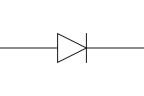
    This diode is drawn upright with its labels hidden. Which end is the anode?

    A triangle pointing up with a short bar across its tip. One lead goes up from the bar and another goes down from the triangle's flat base.

    Not this one Right Answer

    The answer is “The bottom end: it is the end opposite the bar”. The diode's triangle points the way conventional current flows through it during forward conduction, from anode to cathode. The triangle does not say whether the diode is conducting: that depends on the anode's potential relative to the cathode.The cathode (K) is the terminal at the bar. During forward conduction, conventional current leaves the diode at the cathode.Rotating or mirroring a whole symbol, with its terminal identities and connections preserved, does not change the component. The terminal labels move with the drawing. The anode (A) is the terminal opposite the bar. During forward conduction, conventional current enters the diode at the anode.

  3. Question 3

    Three wires meet in a T with no dot drawn. Are they connected?

    Not this one Right Answer

    The answer is “Yes: wires that meet in a T are connected”. In the drawing convention used here, a dot marks a wire connection and a plain four-way crossing without a dot is not connected. Older drawings may use another convention, so check their legend. Wires that meet in a T are connected whether or not a dot is drawn there. Where four wires cross and connect, the dot is what shows it.

  4. Question 4

    What does NC mean on this relay?

    COMNCNOA1A2

    Upper part: a lead labelled COM comes in from the left and ends in a hinged arm. On the right are two contacts, the upper labelled NC and the lower NO, and the arm rests against the upper one. Lower part: a row of loops between leads labelled A1 and A2. A dashed line runs from the loops up to the arm.

    COMNCNOA1A2

    Upper part: a lead labelled COM comes in from the left and ends in a hinged arm. On the right are two contacts, the upper labelled NC and the lower NO, and the arm rests against the upper one. Lower part: a rectangle between leads labelled A1 and A2. A dashed line runs from the rectangle up to the arm.

    Not this one Right Answer

    The answer is “Normally closed: joined to COM while the coil is de-energised”. NC has two unrelated meanings. At a switch or relay contact it means normally closed; on an integrated-circuit pin diagram, nc marks a pin that is not connected.For the non-latching relay shown here, normal means the coil is de-energised. NO contacts are drawn open and NC contacts closed; these labels describe their resting positions. NC is the normally-closed contact: it is connected to COM in the resting, de-energised state of the single-stable relay shown here.

  5. Question 5

    In the drawings here, is this the only mark for ground?

    A vertical lead ending in three horizontal lines, one under another, each shorter than the one above it.

    Not this one Right Answer

    The answer is “No: chassis and signal reference have marks of their own”. This sheet distinguishes earth, chassis and signal reference. They can be connected in a circuit, but the three labels have different meanings; ground does not always mean a connection to earth.The signal-reference symbol marks the chosen zero-volt reference for circuit voltages. It need not be connected to earth or chassis. The three reference marks differ in shape: earth is three horizontal lines getting shorter, chassis is a line with slanted strokes below it, and the signal reference is an open triangle pointing down.

Answer key: Mixed: across the legend

  1. 1

    One resistor, drawn in two styles

  2. 2

    The bottom end: it is the end opposite the bar

  3. 3

    Yes: wires that meet in a T are connected

  4. 4

    Normally closed: joined to COM while the coil is de-energised

  5. 5

    No: chassis and signal reference have marks of their own

Read the circuit symbols chart page and its sources

Resistor symbol

Resistor symbol

  1. Question 1

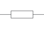
    Which drawing style shows a resistor like this?

    12

    A plain rectangle with a lead out to each side, labelled 1 on the left and 2 on the right.

    Not this one Right Answer

    The answer is “IEC style”. US style names the American drawing convention used here, including the resistor zigzag. IEEE 315-1975 (ANSI Y32.2) is a historical reference; IEEE lists it as inactive-reserved, with inactivation dated 7 November 2019.Three IEC symbols are rectangles: a plain rectangle is a resistor, a rectangle with a line running through it end to end is a fuse, and a rectangle joined by a dashed line to a contact is a relay coil. A resistor symbol stands for a component that opposes current. The zigzag (US style) and the plain rectangle (IEC style) are two drawings of the same component.

  2. Question 2

    What does this drawing show?

    12

    A zigzag line with a lead out to each side, labelled 1 and 2, and a diagonal arrow drawn right through it.

    Not this one Right Answer

    The answer is “A variable resistor”. An arrow drawn right through a resistor body marks a variable resistor with two terminals. An arrow that stops on the body is a wiper, the movable third terminal of a potentiometer.The textbooks cited here mark a thermistor in two ways: a line through the body that ends in a short flat foot rather than an arrowhead, or the letters t° beside the body. Either marks a resistance that changes with temperature; neither says whether it is NTC or PTC. A diagonal arrow through the resistor body marks a variable resistor.

  3. Question 3

    This resistor is drawn upright instead of across the page. Which terminal is positive now?

    12

    A zigzag line drawn upright, with a lead going up, labelled 1, and a lead going down, labelled 2.

    Not this one Right Answer

    The answer is “Neither: a fixed resistor has no polarity”. This symbol has two terminals and no polarity mark. The labels 1 and 2 only tell the two ends apart.Rotating or mirroring a whole symbol, with its terminal identities and connections preserved, does not change the component. The terminal labels move with the drawing. A fixed resistor has two interchangeable terminals; the symbol has no polarity.

  4. Question 4

    Its labels are hidden. What is this part?

    A plain rectangle with a lead out to each side, and a third lead coming down from above that ends in an arrowhead touching the top of the rectangle.

    Not this one Right Answer

    The answer is “A potentiometer”. A rheostat uses only two terminals, one end of the track and the wiper, where a potentiometer brings out all three: both track ends and the wiper.An arrow drawn right through a resistor body marks a variable resistor with two terminals. An arrow that stops on the body is a wiper, the movable third terminal of a potentiometer.Two arrows arriving at a resistor body mark a light-dependent resistor (photoresistor). A potentiometer has three terminals: the two ends of the resistive track and a wiper, drawn as an arrow touching the body.

  5. Question 5

    A thermistor is drawn with no other marking beside it. Does its resistance rise or fall as it warms?

    12

    A plain rectangle with a lead out to each side, labelled 1 and 2. A line runs diagonally up through it from a short flat foot at the lower left, and the letters t° sit beside its upper end.

    Not this one Right Answer

    The answer is “You cannot tell from the symbol alone”. The textbooks cited here mark a thermistor in two ways: a line through the body that ends in a short flat foot rather than an arrowhead, or the letters t° beside the body. Either marks a resistance that changes with temperature; neither says whether it is NTC or PTC.The textbooks cited here mark a thermistor in two ways: a line through the body that ends in a short flat foot rather than an arrowhead, or the letters t° beside the body. Either marks a resistance that changes with temperature; neither says whether it is NTC or PTC. A thermistor's resistance changes with temperature. NTC resistance falls as temperature rises; PTC resistance rises. A generic thermistor symbol without a type label does not distinguish the two.

Answer key: Resistor symbol

  1. 1

    IEC style

  2. 2

    A variable resistor

  3. 3

    Neither: a fixed resistor has no polarity

  4. 4

    A potentiometer

  5. 5

    You cannot tell from the symbol alone

Read the resistor symbol page and its sources

Capacitor symbol

Capacitor symbol

  1. Question 1

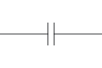
    Which component is this?

    12

    Two parallel vertical lines of equal length, with a lead from the middle of each: labelled 1 on the left and 2 on the right.

    Not this one Right Answer

    The answer is “A capacitor”. In a cell symbol the long thin line is the positive terminal and the short thick line is the negative terminal.In the polarised capacitor drawings here, + marks the positive terminal. The US form has a curved negative plate; the IEC form has a hollow positive plate. The marked polarity must be respected. A cell and a capacitor are both drawn as two parallel lines. In a cell, and in each cell of a battery, the lines differ in length and the long line is the positive terminal; a capacitor's two plates are drawn the same length, and only a polarised capacitor adds a polarity mark.

  2. Question 2

    What does the arrow through this capacitor mean?

    12

    Two parallel vertical lines of equal length with a lead from each, labelled 1 and 2, and a diagonal arrow drawn up through both lines.

    Not this one Right Answer

    The answer is “Its capacitance can be adjusted”. A non-polarised capacitor has two interchangeable terminals.A cell and a capacitor are both drawn as two parallel lines. In a cell, and in each cell of a battery, the lines differ in length and the long line is the positive terminal; a capacitor's two plates are drawn the same length, and only a polarised capacitor adds a polarity mark. In the variable-capacitor convention used here, a diagonal arrow through the plates indicates adjustable capacitance.

  3. Question 3

    The labels on this capacitor are hidden. Is it polarised?

    A straight vertical line on the left and a curved line on the right whose middle bows toward it, with a lead from each and a small plus sign above and to the left of the straight line.

    Not this one Right Answer

    The answer is “Yes: the curved plate and the + mark it”. The − terminal is the other side of the marked polarity. In the US form here it connects to the curved plate; in the IEC form, to the plate opposite the hollow one.Most electrolytic capacitors are polarised: voltage of the wrong polarity can damage their very thin oxide insulating layer, so they are marked to show their polarity. The two words are not interchangeable, since non-polarised electrolytic capacitors also exist and are usually marked NP. In the polarised capacitor drawings here, + marks the positive terminal. The US form has a curved negative plate; the IEC form has a hollow positive plate. The marked polarity must be respected.

  4. Question 4

    Does the + on a schematic tell you which lead of the real capacitor is positive?

    Not this one Right Answer

    The answer is “No: read the marking on the part itself”. A schematic symbol shows how terminals connect, not where they are on a real part. Terminal letters such as E, B and C or A and K do not give lead order or package layout; the part's own documentation does.Many electrolytic capacitors are marked for polarity on the part itself, typically with a − sign beside the negative lead, often printed on a stripe down the can. That marking belongs to the part, not the schematic, and it is not uniform: some parts mark the positive terminal instead, and a stripe on a non-polarised film capacitor means something else. A capacitor's + mark identifies its positive electrical terminal. A schematic does not specify physical lead length or package pinout; those require the component's own markings and documentation.

  5. Question 5

    In this IEC-style drawing, what does the hollow plate mark?

    A narrow hollow rectangle on the left and a straight vertical line on the right, with a lead from each and a small plus sign above and to the left of the rectangle.

    Not this one Right Answer

    The answer is “The positive plate”. The − terminal is the other side of the marked polarity. In the US form here it connects to the curved plate; in the IEC form, to the plate opposite the hollow one.In the variable-capacitor convention used here, a diagonal arrow through the plates indicates adjustable capacitance. The + terminal is the one the polarity mark names as positive. In the US form here it connects to the straight plate; in the IEC form, to the hollow plate.

Answer key: Capacitor symbol

  1. 1

    A capacitor

  2. 2

    Its capacitance can be adjusted

  3. 3

    Yes: the curved plate and the + mark it

  4. 4

    No: read the marking on the part itself

  5. 5

    The positive plate

Read the capacitor symbol page and its sources

Diode symbol

Diode symbol

  1. Question 1

    The labels on this diode are hidden. Which end is the cathode?

    A triangle pointing down with a short bar across its tip. One lead goes up from the triangle's flat base and another goes down from the bar.

    Not this one Right Answer

    The answer is “The bar end”. A schematic symbol shows how terminals connect, not where they are on a real part. Terminal letters such as E, B and C or A and K do not give lead order or package layout; the part's own documentation does.Rotating or mirroring a whole symbol, with its terminal identities and connections preserved, does not change the component. The terminal labels move with the drawing.The anode (A) is the terminal opposite the bar. During forward conduction, conventional current enters the diode at the anode. The cathode (K) is the terminal at the bar. During forward conduction, conventional current leaves the diode at the cathode.

  2. Question 2

    Read the voltage applied to each end. Under the ideal model, is this diode forward or reverse biased?

    AKapplied+12 Vapplied+5 V

    A triangle pointing right with a short bar across its tip. The left-hand lead is labelled A, applied +12 V; the right-hand lead, at the bar, is labelled K, applied +5 V.

    Not this one Right Answer

    The answer is “Forward biased: the anode is more positive than the cathode”. The cathode is a terminal name, not a permanently negative terminal. During forward conduction conventional current leaves it. A cathode can be at +5 V while the anode is more positive.A diode is forward biased when its anode potential is higher than its cathode potential, and reverse biased when the cathode is higher. Page orientation does not decide bias; the current also depends on the model and connected circuit. The applied anode-side potential is higher: this is a forward-bias comparison. The ideal model permits anode-to-cathode current in the stated current-limited test; the applied values are not loaded diode voltages.

  3. Question 3

    This diode is drawn pointing left. What decides whether it is forward or reverse biased?

    AK

    A triangle pointing left with a short bar across its tip. The lead at the bar, on the left, is labelled K; the lead on the right is labelled A.

    Not this one Right Answer

    The answer is “The anode's voltage compared with the cathode's”. The diode's triangle points the way conventional current flows through it during forward conduction, from anode to cathode. The triangle does not say whether the diode is conducting: that depends on the anode's potential relative to the cathode.Rotating or mirroring a whole symbol, with its terminal identities and connections preserved, does not change the component. The terminal labels move with the drawing. A diode is forward biased when its anode potential is higher than its cathode potential, and reverse biased when the cathode is higher. Page orientation does not decide bias; the current also depends on the model and connected circuit.

  4. Question 4

    Which kind of diode is this?

    AK

    A triangle pointing right with a short bar across its tip, leads labelled A on the left and K on the right, and two small arrows pointing away from the triangle.

    Not this one Right Answer

    The answer is “A light-emitting diode (LED)”. An LED and a photodiode differ only in the direction of their two arrows: an LED's point away from the body, for light given out, and a photodiode's point toward it, for light received.Every diode variant here keeps the triangle and bar and adds one mark: arrows leaving the body for an LED, arrows arriving for a photodiode, bent bar ends for a Zener and hooked bar ends for a Schottky. With no added mark it is a generic diode.Zener and Schottky symbols differ only at the cathode bar: a Zener bar has bent ends and a Schottky bar has hooked ends. Two arrows leaving the diode body mark a light-emitting diode.

  5. Question 5

    Compare the two applied voltages. Under the ideal model, what is the diode doing?

    AKapplied0 Vapplied+5 V

    A triangle pointing right with a short bar across its tip. The left-hand lead is labelled A, applied 0 V; the right-hand lead, at the bar, is labelled K, applied +5 V.

    Not this one Right Answer

    The answer is “Reverse biased, so it blocks”. A diode is forward biased when its anode potential is higher than its cathode potential, and reverse biased when the cathode is higher. Page orientation does not decide bias; the current also depends on the model and connected circuit.The diode's triangle points the way conventional current flows through it during forward conduction, from anode to cathode. The triangle does not say whether the diode is conducting: that depends on the anode's potential relative to the cathode. The applied anode-side potential is lower: this is a reverse-bias comparison. The ideal diode model blocks reverse current.

Answer key: Diode symbol

  1. 1

    The bar end

  2. 2

    Forward biased: the anode is more positive than the cathode

    AKapplied+12 Vapplied+5 V
  3. 3

    The anode's voltage compared with the cathode's

  4. 4

    A light-emitting diode (LED)

  5. 5

    Reverse biased, so it blocks

    AKapplied0 Vapplied+5 V

Read the diode symbol page and its sources

Transistor symbol

Transistor symbol

  1. Question 1

    This transistor has been turned and its labels hidden. Which lead is its emitter?

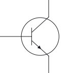
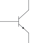
    A short horizontal bar with a lead rising straight up from its middle. Two angled leads run down from the bar, one to each side, and bend out sideways; the left-hand one carries an arrow pointing away from the bar. A circle surrounds the drawing.

    A short horizontal bar with a lead rising straight up from its middle. Two angled leads run down from the bar, one to each side, and bend out sideways; the left-hand one carries an arrow pointing away from the bar.

    Not this one Right Answer

    The answer is “The lead on the left”. The base is the terminal drawn against the flat bar; a small base current controls the device.The collector is the branch connected to the base bar that has no emitter arrow. The base has its own separate lead to that bar. The arrow is always on the emitter. It points out of the transistor for NPN and into it for PNP, whichever way the symbol is rotated.

  2. Question 2

    Which transistor is this?

    A short vertical bar with a lead coming in from the right. Two angled leads leave the bar on the left and bend away, one up and one down, and the upper one carries an arrow pointing toward the bar. A circle surrounds the drawing.

    A short vertical bar with a lead coming in from the right. Two angled leads leave the bar on the left and bend away, one up and one down, and the upper one carries an arrow pointing toward the bar.

    Not this one Right Answer

    The answer is “A PNP bipolar transistor”. The arrow is always on the emitter. It points out of the transistor for NPN and into it for PNP, whichever way the symbol is rotated.A MOSFET's gate is drawn beside the channel with a gap between them, and its arrow sits on the body. A bipolar transistor's base lead meets its bar directly, and its arrow sits on the angled emitter lead. In a PNP transistor symbol the emitter arrow points in, toward the base; that inward arrow is the only mark that tells it from an NPN symbol.

  3. Question 3

    This transistor is drawn inside a circle. What would the drawing mean without it?

    BCE

    A circle round a short vertical bar. A lead from the left, labelled B, meets the bar; two angled leads leave it, one up to a lead labelled C and one down to a lead labelled E, and the lower one carries an arrow pointing away from the bar.

    Not this one Right Answer

    The answer is “The same transistor: the circle is optional”. In a PNP transistor symbol the emitter arrow points in, toward the base; that inward arrow is the only mark that tells it from an NPN symbol.A MOSFET's gate is drawn beside the channel with a gap between them, and its arrow sits on the body. A bipolar transistor's base lead meets its bar directly, and its arrow sits on the angled emitter lead. The enclosing circle may be omitted from a transistor symbol. With the same internal marks and terminal connections, either drawing represents the same transistor.

  4. Question 4

    The base is driven, as marked. Under the switch model, what is the collector–emitter path doing?

    BCEdriven

    A lead from the left, labelled B and marked driven, meets a short vertical bar; two angled leads leave the bar, one up to a lead labelled C and one down to a lead labelled E, and the lower one carries an arrow pointing away from the bar. A circle surrounds the drawing.

    BCEdriven

    A lead from the left, labelled B and marked driven, meets a short vertical bar; two angled leads leave the bar, one up to a lead labelled C and one down to a lead labelled E, and the lower one carries an arrow pointing away from the bar.

    Not this one Right Answer

    The answer is “Conducting: the transistor is on”. The emitter arrow points the way conventional current flows through the emitter when the transistor conducts: out of an NPN transistor and into a PNP. Base and collector currents combine to match the arrow's direction.Under the BJT switch model, suitable circuit bias and sufficient base drive put the transistor in saturation; no base drive gives cutoff. The cases omit leakage, transition time and the active amplification region. Under the BJT switch model, sufficient base drive for the connected load gives saturation: the collector–emitter path conducts.

  5. Question 5

    This MOSFET is drawn turned round, with its labels hidden. Which lead is its gate?

    A vertical line with a lead coming in from the right. To its left, across a small gap, is a broken vertical line of three short dashes. Three horizontal lines run left from the dashes: the top and bottom ones turn to leave as leads going up and down, and the middle one, which carries an arrow pointing toward the dashes, joins the upper lead. A circle surrounds the drawing.

    A vertical line with a lead coming in from the right. To its left, across a small gap, is a broken vertical line of three short dashes. Three horizontal lines run left from the dashes: the top and bottom ones turn to leave as leads going up and down, and the middle one, which carries an arrow pointing toward the dashes, joins the upper lead.

    Not this one Right Answer

    The answer is “The lead on the right”. The source (S) is the channel terminal joined to the body in the three-terminal form shown here, so the controlling gate voltage is applied between gate and source.The drain (D) is the other channel terminal: the channel runs between drain and source. The gate is the insulated terminal drawn parallel to the channel with a gap between them.

Answer key: Transistor symbol

  1. 1

    The lead on the left

  2. 2

    A PNP bipolar transistor

  3. 3

    The same transistor: the circle is optional

  4. 4

    Conducting: the transistor is on

    BCEdriven
    BCEdriven
  5. 5

    The lead on the right

Read the transistor symbol page and its sources

Inductor symbol

Inductor symbol

  1. Question 1

    This coil is drawn as a row of humps rather than loops. What has changed?

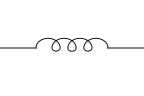
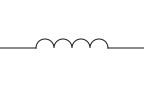
    12

    A row of humps with a lead out to each side, labelled 1 on the left and 2 on the right.

    Not this one Right Answer

    The answer is “Only the drawing style: it is still an inductor”. A transformer has two or more windings drawn facing each other, with core lines between them when it has a magnetic core. An inductor is a single winding with two terminals.In the coil convention used here, solid parallel core lines indicate iron and dashed core lines ferrite. The unmarked coil is used for air core. These drawings do not identify every material detail. Looped and semicircular coil drawings are alternative inductor forms. This sheet uses loops in its US view and humps in its IEC view; the winding and terminal roles are unchanged.

  2. Question 2

    Is this drawing an inductor?

    12

    A zigzag line with a lead out to each side, labelled 1 on the left and 2 on the right.

    Not this one Right Answer

    The answer is “No: a zigzag has no turns, so it is a resistor”. A resistor symbol stands for a component that opposes current. The zigzag (US style) and the plain rectangle (IEC style) are two drawings of the same component.Looped and semicircular coil drawings are alternative inductor forms. This sheet uses loops in its US view and humps in its IEC view; the winding and terminal roles are unchanged. An inductor is drawn as a coil, a row of loops or humps for its turns. A resistor has no turns: it is a zigzag in US drawings and a plain rectangle in IEC drawings.

  3. Question 3

    What do the two straight lines beside this coil mark?

    12

    A row of loops with a lead out to each side, labelled 1 and 2, and two straight lines drawn parallel to it.

    12

    A row of humps with a lead out to each side, labelled 1 and 2, and two straight lines drawn parallel to it.

    Not this one Right Answer

    The answer is “The coil's core”. A transformer has two or more windings drawn facing each other, with core lines between them when it has a magnetic core. An inductor is a single winding with two terminals.A capacitor symbol stands for two conductors separated by an insulator; the two parallel plates are a picture of that. In the coil convention used here, solid parallel core lines indicate iron and dashed core lines ferrite. The unmarked coil is used for air core. These drawings do not identify every material detail.

  4. Question 4

    Read the whole drawing. Which component is it?

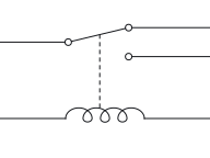
    Upper part: a lead from the left ends in a hinged arm that rests against the upper of two contacts on the right, each contact with its own lead. Lower part: a row of loops between two leads. A dashed line runs from the top of the loops up to the arm.

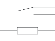
    Upper part: a lead from the left ends in a hinged arm that rests against the upper of two contacts on the right, each contact with its own lead. Lower part: a rectangle between two leads. A dashed line runs from the top of the rectangle up to the arm.

    Not this one Right Answer

    The answer is “A relay”. A looped coil on its own can be an inductor, a solenoid or a relay coil, so what is drawn with it decides: a relay coil is joined to its contacts by a dashed link, and parallel lines beside a coil mark a magnetic core.A transformer has two or more windings drawn facing each other, with core lines between them when it has a magnetic core. An inductor is a single winding with two terminals. A relay symbol combines a coil with the contacts it moves, joined by a dashed mechanical link. US drawings show the coil as loops and IEC drawings as a rectangle; a plain switch has no coil.

  5. Question 5

    Which component does this drawing show?

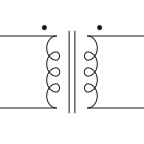
    Two rows of loops facing each other, with two straight parallel lines between them and a dot near the top of each row. The left row's two leads go out to the left and the right row's two leads go out to the right.

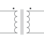
    Two rows of humps facing each other, with two straight parallel lines between them and a dot near the top of each row. The left row's two leads go out to the left and the right row's two leads go out to the right.

    Not this one Right Answer

    The answer is “A transformer”. The separate-winding transformer shown here transfers energy magnetically between windings without an internal conducting connection between them. This description excludes an autotransformer, whose windings share a conducting connection.In the coil convention used here, solid parallel core lines indicate iron and dashed core lines ferrite. The unmarked coil is used for air core. These drawings do not identify every material detail. A transformer has two or more windings drawn facing each other, with core lines between them when it has a magnetic core. An inductor is a single winding with two terminals.

Answer key: Inductor symbol

  1. 1

    Only the drawing style: it is still an inductor

  2. 2

    No: a zigzag has no turns, so it is a resistor

  3. 3

    The coil's core

  4. 4

    A relay

  5. 5

    A transformer

Read the inductor symbol page and its sources

Transformer symbol

Transformer symbol

  1. Question 1

    Is there a wire connection from the primary winding to the secondary in this drawing?

    P1P2S1S2

    Two rows of loops facing each other, with two straight parallel lines between them and a dot near the top of each row. The left row's leads, going left, are labelled P1 at the top and P2 at the bottom; the right row's leads, going right, are labelled S1 and S2.

    P1P2S1S2

    Two rows of humps facing each other, with two straight parallel lines between them and a dot near the top of each row. The left row's leads, going left, are labelled P1 at the top and P2 at the bottom; the right row's leads, going right, are labelled S1 and S2.

    Not this one Right Answer

    The answer is “No: the windings are linked magnetically, not by a wire”. In the transformer drawings here, parallel lines between windings indicate a magnetic core, drawn as iron-core examples. The air-core example omits these lines; another drawing's legend may use a plain coil more generally.An autotransformer is drawn as a single winding with taps rather than separate windings. Its primary and secondary connections share that winding, so there is no electrical isolation between them. The separate-winding transformer shown here transfers energy magnetically between windings without an internal conducting connection between them. This description excludes an autotransformer, whose windings share a conducting connection.

  2. Question 2

    Its labels are hidden. How do you know which winding is the primary?

    Two rows of loops facing each other, with two straight parallel lines between them and a dot near the top of each row. The left row's two leads go out to the left and the right row's two leads go out to the right.

    Two rows of humps facing each other, with two straight parallel lines between them and a dot near the top of each row. The left row's two leads go out to the left and the right row's two leads go out to the right.

    Not this one Right Answer

    The answer is “It is the winding the source drives”. Transformer dots mark corresponding voltage polarity: each dotted terminal has the same instantaneous polarity relative to its own winding's undotted terminal. The dots do not indicate equal voltage or current direction.Rotating or mirroring a whole symbol, with its terminal identities and connections preserved, does not change the component. The terminal labels move with the drawing. The primary winding is the one driven by the source.

  3. Question 3

    What do the dots beside the two windings mark?

    P1P2S1S2

    Two rows of loops facing each other, with two straight parallel lines between them. A dot sits near the top of each row: beside P1 on the left row and beside S1 on the right row.

    P1P2S1S2

    Two rows of humps facing each other, with two straight parallel lines between them. A dot sits near the top of each row: beside P1 on the left row and beside S1 on the right row.

    Not this one Right Answer

    The answer is “Ends with the same polarity at the same instant”. In the drawing convention used here, a dot marks a wire connection and a plain four-way crossing without a dot is not connected. Older drawings may use another convention, so check their legend. Transformer dots mark corresponding voltage polarity: each dotted terminal has the same instantaneous polarity relative to its own winding's undotted terminal. The dots do not indicate equal voltage or current direction.

  4. Question 4

    What is the extra lead from the middle of the secondary winding?

    P1P2S1S2?

    Two rows of loops facing each other, with two straight parallel lines between them. The left row's leads are labelled P1 and P2 and the right row's S1 and S2. A fifth lead, labelled ?, leaves the middle of the right row.

    P1P2S1S2?

    Two rows of humps facing each other, with two straight parallel lines between them. The left row's leads are labelled P1 and P2 and the right row's S1 and S2. A fifth lead, labelled ?, leaves the middle of the right row.

    Not this one Right Answer

    The answer is “A centre tap”. This sheet distinguishes earth, chassis and signal reference. They can be connected in a circuit, but the three labels have different meanings; ground does not always mean a connection to earth.An extra lead joined partway along a coil marks a tapped inductor: the tap is a connection to part of the winding. A centre tap is an electrical connection at the midpoint of a winding, shown as an extra lead from that winding.

  5. Question 5

    No lines are drawn between these two windings. What does that mean in the drawings here?

    P1P2S1S2

    Two rows of loops facing each other with nothing drawn between them. P1 and P2 label the left row's leads, and S1 and S2 the right row's.

    P1P2S1S2

    Two rows of humps facing each other with nothing drawn between them. P1 and P2 label the left row's leads, and S1 and S2 the right row's.

    Not this one Right Answer

    The answer is “An air core: there is no magnetic core”. A transformer has two or more windings drawn facing each other, with core lines between them when it has a magnetic core. An inductor is a single winding with two terminals.The separate-winding transformer shown here transfers energy magnetically between windings without an internal conducting connection between them. This description excludes an autotransformer, whose windings share a conducting connection. In the transformer drawings here, parallel lines between windings indicate a magnetic core, drawn as iron-core examples. The air-core example omits these lines; another drawing's legend may use a plain coil more generally.

Answer key: Transformer symbol

  1. 1

    No: the windings are linked magnetically, not by a wire

  2. 2

    It is the winding the source drives

  3. 3

    Ends with the same polarity at the same instant

  4. 4

    A centre tap

  5. 5

    An air core: there is no magnetic core

Read the transformer symbol page and its sources

Switch symbol

Switch symbol

  1. Question 1

    Count the moving arms and the contacts each one can reach. What kind of switch is this?

    Two identical sections, one above the other. In each, a lead from the left ends in a hinged arm that rests against the upper of two contacts on the right, and each contact has its own lead going right. A dashed line joins the two arms.

    Two identical sections, one above the other. In each, a lead from the left ends in a hinged arm that rests against the upper of two contacts on the right, and each contact has its own lead going right. A dashed line joins the two arms.

    Not this one Right Answer

    The answer is “DPDT”. Count the arms and look for a coil: an SPDT switch has one arm between two fixed contacts, a DPDT switch has two arms tied by a dashed link, and a relay adds a coil linked to its contacts.A double-pole, single-throw (DPST) switch has two moving poles worked by one mechanism, each closing onto its own fixed contact. It acts like two SPST switches linked together.A dashed line joining parts of a symbol shows a mechanical link: the parts move together, but the line is not a wire and carries no current. A double-pole, double-throw (DPDT) switch works like two SPDT switches ganged together. The dashed line between its two arms is a mechanical link: the arms move together, but no current passes along it.

  2. Question 2

    How many throws does this switch have?

    A lead comes down from the top and ends in a hinged arm that swings clear of a single contact below it. That contact's lead carries on down.

    A lead comes down from the top and ends in a hinged arm that swings clear of a single contact below it. That contact's lead carries on down.

    Not this one Right Answer

    The answer is “One: the contact the arm closes onto”. Poles count the separate circuits a switch controls; throws count the contact destinations available to each pole. An off position is not an additional throw.Poles count the separate circuits a switch controls; throws count the contact destinations available to each pole. An off position is not an additional throw. In a switch symbol the moving arm is the pole, and each fixed contact it can close onto is a throw.

  3. Question 3

    Is this push button normally open or normally closed?

    A horizontal bar resting across two contacts, one with a lead to the left and one with a lead to the right. A short vertical stem rises from the middle of the bar to a small cap.

    A horizontal bar resting across two contacts, one with a lead to the left and one with a lead to the right. A short vertical stem rises from the middle of the bar to a small cap.

    Not this one Right Answer

    The answer is “Normally closed”. Switch contacts are drawn in their normal status: the position they rest in with no force applied. A normally-open (NO) contact is drawn open and a normally-closed (NC) contact closed; for a momentary push button, normal means not pressed.The momentary-switch model has two settled states: released, with the contacts in their drawn normal status, and pressed, with each contact in the opposite state. It leaves out contact bounce, contact resistance and latching. The two push buttons differ only in the resting position drawn: the normally-open bar is drawn clear of its contacts and the normally-closed bar touching them. Pressing reverses each one; the drawing does not change.

  4. Question 4

    This switch is set to the position it is drawn in. Under the ideal-contact model, is there a conducting path between its two terminals?

    12

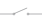
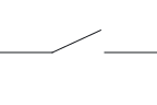
    A lead from the left, labelled 1, ends in a hinged arm that is lifted clear of the contact on the right, whose lead is labelled 2.

    12

    A lead from the left, labelled 1, ends in a hinged arm that is lifted clear of the contact on the right, whose lead is labelled 2.

    Not this one Right Answer

    The answer is “No: the arm is lifted clear”. The ideal-contact model treats an open contact as electrically isolating, so no current passes, and a closed contact as making its two terminals electrically common, with no voltage between them. It leaves out contact bounce and contact resistance.The ideal-contact model treats an open contact as electrically isolating, so no current passes, and a closed contact as making its two terminals electrically common, with no voltage between them. It leaves out contact bounce and contact resistance. Under the ideal-contact model, an open switch breaks the conducting path between its two terminals.

  5. Question 5

    What happens when you let go of this push button?

    12

    A horizontal bar held above two contacts without touching them, one contact with a lead to the left, labelled 1, and one with a lead to the right, labelled 2. A short stem topped by a small cap rises from the middle of the bar.

    12

    A horizontal bar held above two contacts without touching them, one contact with a lead to the left, labelled 1, and one with a lead to the right, labelled 2. A short stem topped by a small cap rises from the middle of the bar.

    Not this one Right Answer

    The answer is “It returns to the position it is drawn in”. A momentary switch has an internal spring that returns it to its resting position as soon as it is released. A switch without that spring, such as a knife switch or most toggle switches, stays wherever it was last put.The two push buttons differ only in the resting position drawn: the normally-open bar is drawn clear of its contacts and the normally-closed bar touching them. Pressing reverses each one; the drawing does not change. The momentary push buttons shown here change contact state while pressed and return to their drawn, unactuated state when released.

Answer key: Switch symbol

  1. 1

    DPDT

  2. 2

    One: the contact the arm closes onto

  3. 3

    Normally closed

  4. 4

    No: the arm is lifted clear

    12
    12
  5. 5

    It returns to the position it is drawn in

Read the switch symbol page and its sources

Relay symbol

Relay symbol

  1. Question 1

    The coil is de-energised. Which contacts are joined?

    COMNCNOA1A2

    Upper part: a lead labelled COM comes in from the left and ends in a hinged arm. On the right are two contacts, the upper labelled NC and the lower NO, and the arm is drawn against the upper one. Lower part: a row of loops between leads labelled A1 and A2. A dashed line runs from the loops up to the arm.

    COMNCNOA1A2

    Upper part: a lead labelled COM comes in from the left and ends in a hinged arm. On the right are two contacts, the upper labelled NC and the lower NO, and the arm is drawn against the upper one. Lower part: a rectangle between leads labelled A1 and A2. A dashed line runs from the rectangle up to the arm.

    Not this one Right Answer

    The answer is “COM and NC”. For the non-latching relay shown here, normal means the coil is de-energised. NO contacts are drawn open and NC contacts closed; these labels describe their resting positions.COM is the common contact, the one the moving arm belongs to.NC is the normally-closed contact: it is connected to COM in the resting, de-energised state of the single-stable relay shown here. Under the single-stable relay model, the coil is de-energised and settled: COM–NC is closed and COM–NO is open. This is the drawn resting state.

  2. Question 2

    The coil is now energised. What happens to the printed NO and NC labels?

    COMNCNOA1A2

    The relay as printed: COM on the left, NC upper right, NO lower right, the arm drawn against NC, and a row of loops between A1 and A2 with a dashed line up to the arm. A highlight marks the coil as energised and shows COM joined to NO; the printed arm and labels are unchanged.

    COMNCNOA1A2

    The relay as printed: COM on the left, NC upper right, NO lower right, the arm drawn against NC, and a rectangle between A1 and A2 with a dashed line up to the arm. A highlight marks the coil as energised and shows COM joined to NO; the printed arm and labels are unchanged.

    Not this one Right Answer

    The answer is “Nothing: they name the resting positions”. For the non-latching relay shown here, normal means the coil is de-energised. NO contacts are drawn open and NC contacts closed; these labels describe their resting positions.In every case the printed relay contact stays drawn in its resting, de-energised position, and the NO and NC labels stay where they are. Only the highlight shows the present position. In the single-stable changeover relay shown here, energising the coil transfers COM from NC to NO after the operating delay. The printed symbol and its NO/NC labels remain unchanged.

  3. Question 3

    The contact labels are hidden. What is the terminal on the moving arm called?

    ???A1A2

    Upper part: a lead labelled ? comes in from the left and ends in a hinged arm. On the right are two contacts, each labelled ?, and the arm is drawn against the upper one. Lower part: a rectangle between leads labelled A1 and A2. A dashed line runs from the rectangle up to the arm.

    Not this one Right Answer

    The answer is “COM”. NO is the normally-open contact: it is disconnected from COM at rest and connected after the coil has energised the single-stable relay shown here.NC is the normally-closed contact: it is connected to COM in the resting, de-energised state of the single-stable relay shown here.The two coil terminals are the control side of the relay; the current that flows through them moves the contacts. COM is the common contact, the one the moving arm belongs to.

  4. Question 4

    What does the dashed line between the coil and the contact carry?

    COMNCNOA1A2

    Upper part: a lead labelled COM comes in from the left and ends in a hinged arm, drawn against the upper of two contacts labelled NC and NO. Lower part: a row of loops between leads labelled A1 and A2. A dashed line runs from the top of the loops up to the arm.

    Not this one Right Answer

    The answer is “No current: it is a mechanical link”. A dashed line joining parts of a symbol shows a mechanical link: the parts move together, but the line is not a wire and carries no current.The electromechanical relay shown here uses a coil to move contacts. Its coil circuit is electrically separate from the switched contact circuit. The dashed line between coil and contact is the mechanical link; it carries no current.

  5. Question 5

    Automotive relays often number their terminals 85, 86, 30, 87 and 87a. Which number names the common contact?

    Not this one Right Answer

    The answer is “30”. Automotive relays often carry numbers from the German DIN 72552 terminal scheme instead of COM, NO and NC: 85 and 86 are the coil terminals, 30 is the common contact, 87 the normally-open contact and 87a the normally-closed contact.

Answer key: Relay symbol

  1. 1

    COM and NC

    COMNCNOA1A2
    COMNCNOA1A2
  2. 2

    Nothing: they name the resting positions

  3. 3

    COM

  4. 4

    No current: it is a mechanical link

  5. 5

    30

Read the relay symbol page and its sources

Ground symbol

Ground symbol

  1. Question 1

    Which kind of reference does this mark stand for?

    A vertical lead ending in three horizontal lines, one under another, each shorter than the one above it.

    Not this one Right Answer

    The answer is “Earth”. The three reference marks differ in shape: earth is three horizontal lines getting shorter, chassis is a line with slanted strokes below it, and the signal reference is an open triangle pointing down.The chassis symbol (hatched) marks a connection to the equipment's metal frame or enclosure. In the convention used here, three horizontal lines of decreasing length identify a connection to earth. Check a drawing's legend: the same shape is sometimes used more generally for circuit ground.

  2. Question 2

    What is this reference mark connected to?

    A vertical lead ending in a horizontal line with three short slanted strokes hanging below it.

    Not this one Right Answer

    The answer is “The equipment's metal frame or enclosure”. This sheet distinguishes earth, chassis and signal reference. They can be connected in a circuit, but the three labels have different meanings; ground does not always mean a connection to earth.The three reference marks differ in shape: earth is three horizontal lines getting shorter, chassis is a line with slanted strokes below it, and the signal reference is an open triangle pointing down. The chassis symbol (hatched) marks a connection to the equipment's metal frame or enclosure.

  3. Question 3

    Does this reference mark, on its own, connect the circuit to earth?

    A vertical lead ending in an open triangle that points down.

    Not this one Right Answer

    The answer is “No: it marks the circuit's 0 V reference”. This sheet distinguishes earth, chassis and signal reference. They can be connected in a circuit, but the three labels have different meanings; ground does not always mean a connection to earth.A label such as GND, Gnd or 0 V at a reference symbol names the node that other potentials are measured from. A drawing may keep separate commons, such as an analog signal common and a digital logic common, so differently named references must not be assumed to be joined. The signal-reference symbol marks the chosen zero-volt reference for circuit voltages. It need not be connected to earth or chassis.

  4. Question 4

    On one sheet, a reference symbol labelled AGND marks the analog common and another labelled DGND marks the digital common. No wire is drawn between them. Are they one node?

    Not this one Right Answer

    The answer is “No: references with different names are not assumed joined”. Within the drawing's stated scope, repeated supply or reference labels identify the same node without a drawn wire between them. Different labels or reference symbols must not be assumed connected.Within the drawing's stated scope, repeated supply or reference labels identify the same node without a drawn wire between them. Different labels or reference symbols must not be assumed connected. A label such as GND, Gnd or 0 V at a reference symbol names the node that other potentials are measured from. A drawing may keep separate commons, such as an analog signal common and a digital logic common, so differently named references must not be assumed to be joined.

  5. Question 5

    How many connections does this earth symbol make to the circuit?

    A lead coming in from the right and ending in three vertical lines side by side, each shorter than the one before as they go left.

    Not this one Right Answer

    The answer is “One, at the end of its lead”. The three reference marks differ in shape: earth is three horizontal lines getting shorter, chassis is a line with slanted strokes below it, and the signal reference is an open triangle pointing down.A ground or reference symbol marks a connection to the circuit's common reference, not a part, so the drawings here give it no reference designator. A label such as GND or 0 V names that node instead. Each ground or reference symbol shown here has one connection point to the circuit; it identifies a reference connection, not a two-terminal component.

Answer key: Ground symbol

  1. 1

    Earth

  2. 2

    The equipment's metal frame or enclosure

  3. 3

    No: it marks the circuit's 0 V reference

  4. 4

    No: references with different names are not assumed joined

  5. 5

    One, at the end of its lead

Read the ground symbol page and its sources

Battery symbol

Battery symbol

  1. Question 1

    This cell has been turned round and its labels hidden. Which line is its positive terminal?

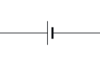
    Two horizontal lines, one above the other: the lower line is long and thin, the upper line short and thick. A lead goes up from the upper line and down from the lower one.

    Not this one Right Answer

    The answer is “The longer, thinner line”. Rotating or mirroring a whole symbol, with its terminal identities and connections preserved, does not change the component. The terminal labels move with the drawing.A cell and a capacitor are both drawn as two parallel lines. In a cell, and in each cell of a battery, the lines differ in length and the long line is the positive terminal; a capacitor's two plates are drawn the same length, and only a polarised capacitor adds a polarity mark. In a cell symbol the long thin line is the positive terminal and the short thick line is the negative terminal.

  2. Question 2

    What does this drawing stand for?

    Two pairs of vertical lines in a row, each pair a long thin line and a short thick line, with a lead out to the left and a lead out to the right.

    Not this one Right Answer

    The answer is “A battery of several cells”. A cell is one long-and-short pair of lines; a battery repeats the pair, drawn as several cells in a row. Both follow the same rule: the long line is positive.A cell and a capacitor are both drawn as two parallel lines. In a cell, and in each cell of a battery, the lines differ in length and the long line is the positive terminal; a capacitor's two plates are drawn the same length, and only a polarised capacitor adds a polarity mark. A battery is drawn as several cells in a row; the terminals follow the same long-positive rule.

  3. Question 3

    Which source does this circle stand for?

    12

    A circle with a single sine wave inside and a lead out to each side, labelled 1 on the left and 2 on the right.

    Not this one Right Answer

    The answer is “An AC voltage source”. The three source circles are told apart by the mark inside: + and − signs for a DC voltage source, a sine wave for an AC voltage source and an arrow for a current source.The generic current-source drawing used in both views is a circle with an arrow giving conventional current direction. An ideal current source fixes that current; the arrow does not give voltage polarity. The sinusoidal AC voltage-source drawing used here is a circle with a sine wave inside.

  4. Question 4

    What does the arrow inside this source circle tell you?

    12

    A circle with an arrow inside pointing from left to right, and a lead out to each side, labelled 1 on the left and 2 on the right.

    Not this one Right Answer

    The answer is “The direction of the current through the source”. A diagonal arrow through a symbol marks it as adjustable, whatever the component, so the body under the arrow says what it is: plates for a variable capacitor, a zigzag or rectangle for a variable resistor, a coil for a variable inductor.Conventional current leaves the ideal current source at the arrowhead end; this does not specify that terminal's voltage polarity. The generic current-source drawing used in both views is a circle with an arrow giving conventional current direction. An ideal current source fixes that current; the arrow does not give voltage polarity.

  5. Question 5

    The labels on this source are hidden. Which terminal is at the higher potential?

    A circle with a lead out to each side. Inside the circle, a plus sign sits toward the right-hand lead and a minus sign toward the left-hand lead.

    Not this one Right Answer

    The answer is “The one beside the + sign”. Rotating or mirroring a whole symbol, with its terminal identities and connections preserved, does not change the component. The terminal labels move with the drawing.The sinusoidal AC voltage source shown here alternates its polarity between its two terminals; neither terminal is permanently positive. The + mark identifies the higher-potential terminal relative to the − terminal. The polarity marks alone do not determine whether current is entering or leaving the source.

Answer key: Battery symbol

  1. 1

    The longer, thinner line

  2. 2

    A battery of several cells

  3. 3

    An AC voltage source

  4. 4

    The direction of the current through the source

  5. 5

    The one beside the + sign

Read the battery symbol page and its sources

Reading a schematic

Reading a schematic

  1. Question 1

    In the torch circuit, are the cell's + terminal and the lamp's lower terminal on the same node?

    BT1S1DS1

    One loop of wire. On the left is a cell labelled BT1, drawn upright with its long line at the top. The wire from the top of the cell runs to a switch labelled S1 along the top, drawn open, and on to the top of a lamp labelled DS1, a circle with a cross, on the right. The wire from the bottom of the lamp runs along the bottom back to the bottom of the cell.

    BT1S1DS1

    One loop of wire. On the left is a cell labelled BT1, drawn upright with its long line at the top. The wire from the top of the cell runs to a switch labelled S1 along the top, drawn open, and on to the top of a lamp labelled DS1, a circle with a cross, on the right. The wire from the bottom of the lamp runs along the bottom back to the bottom of the cell.

    Not this one Right Answer

    The answer is “No: the switch and the lamp sit between them”. In the ideal-wire schematic model, a node is the set of points connected by uninterrupted wire. Those points share one potential; real wire resistance and other wire effects are omitted.

  2. Question 2

    These two wires cross with no dot. In the convention used here, are they connected?

    Two straight wires crossing at right angles, one horizontal and one vertical, with no dot where they cross.

    Not this one Right Answer

    The answer is “No: without a dot they are not connected”. A small half-circle hop where one wire passes over another also means the wires are not connected. Some drawings put a hop at every unconnected crossing and a dot at every connection, so neither is left to guess. In the newer convention used here, wires that cross with no dot are not connected. Older schematics drew connected wires as a plain crossing and made unconnected wires hop over each other with a small half-circle, so check a drawing's legend.

  3. Question 3

    A part on a schematic is labelled K1. What kind of part is it?

    Not this one Right Answer

    The answer is “A relay”. Reference designators identify parts with class letters and a number. Common letters used here are R resistor, C capacitor, D diode, Q transistor, L inductor, T transformer, S switch, K relay and F fuse; other naming systems exist.

  4. Question 4

    Two stubs on the same schematic are both labelled +5 V, with no wire between them. Are they the same node?

    Not this one Right Answer

    The answer is “Yes: stubs with the same label are one node”. Within the drawing's stated scope, repeated supply or reference labels identify the same node without a drawn wire between them. Different labels or reference symbols must not be assumed connected.A schematic describes electrical connections only, not where parts sit. Parts can be moved or redrawn anywhere on the page without changing the circuit, as long as every connection is kept. A supply connection is often drawn as a short labelled stub or dot, such as +5 V, VCC or VDD, instead of a wire back to the source. The source's other side is taken to be the ground reference, and every stub with the same label is the same node.

  5. Question 5

    A resistor on a schematic is labelled 4k7. What value does that give?

    Not this one Right Answer

    The answer is “4.7 kΩ”. Values printed beside a symbol may put the multiplier letter where the decimal point would be: 4k7 means 4.7 kΩ, 3R9 means 3.9 Ω, 47R means 47 Ω and 2M2 means 2.2 MΩ. IEC 60062 sets out this letter code.

Answer key: Reading a schematic

  1. 1

    No: the switch and the lamp sit between them

  2. 2

    No: without a dot they are not connected

  3. 3

    A relay

  4. 4

    Yes: stubs with the same label are one node

  5. 5

    4.7 kΩ

Read the how to read a schematic page and its sources