Transformer symbol
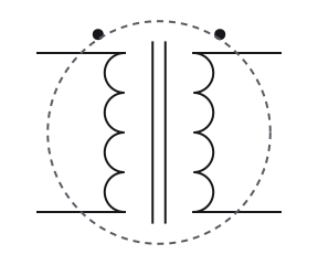
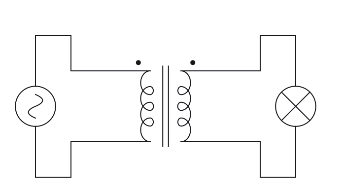
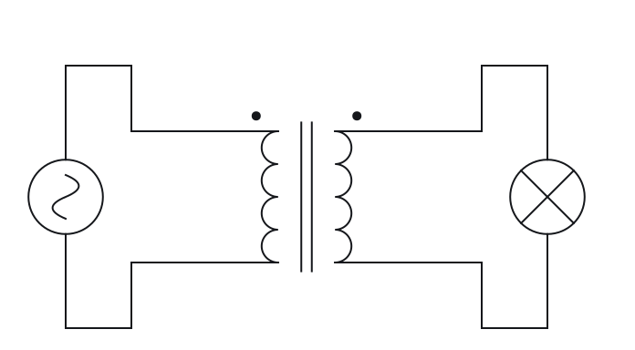
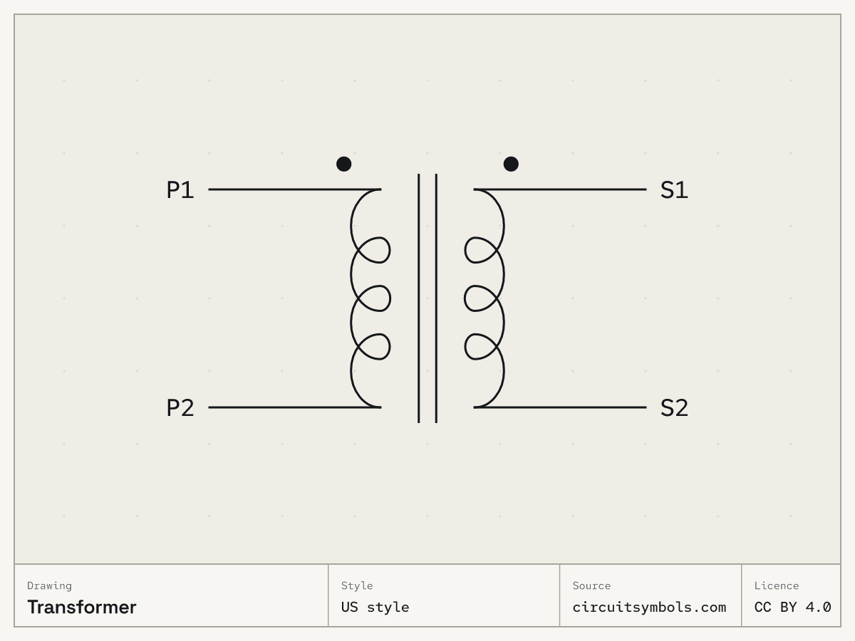
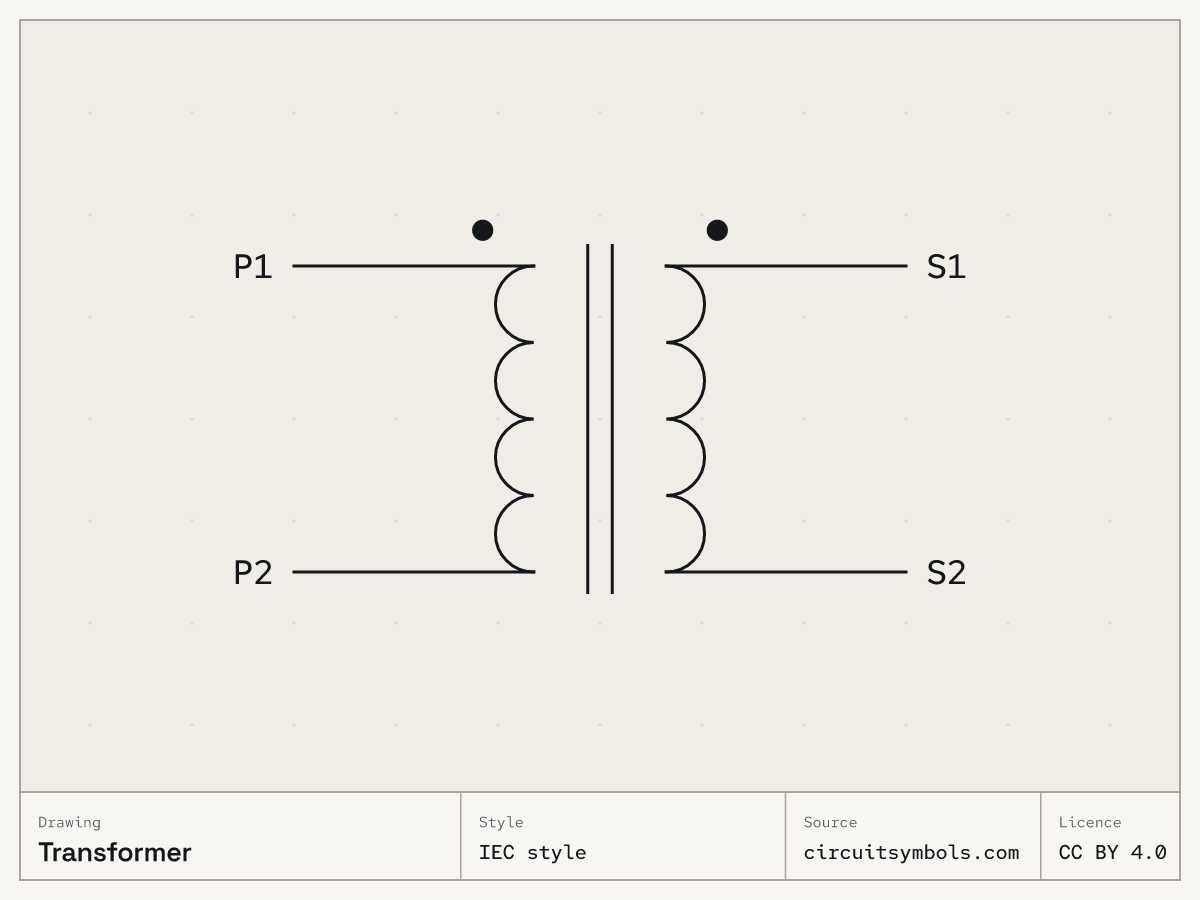
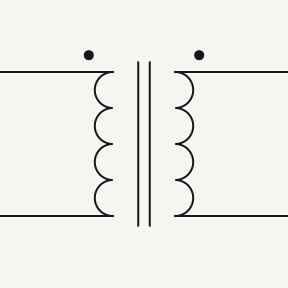
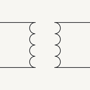
A transformer is drawn as two windings facing each other: the primary, driven by the source, and the secondary, which feeds the load. In the separate-winding form no wire joins them. In the drawings here, lines between them mark a magnetic core.Source 1Source 2Source 3
Symbol and terminals
US style
IEC style
Terminals
Source 1- P1P2
- The primary winding is the one driven by the source.
- S1S2
- The secondary winding is the one that delivers power to the load.
Parts of the drawing
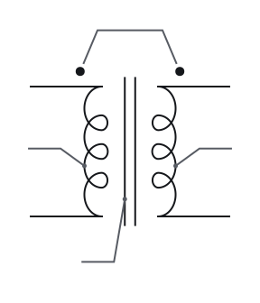
- 1 Dots
- Transformer dots mark corresponding voltage polarity: each dotted terminal has the same instantaneous polarity relative to its own winding's undotted terminal. The dots do not indicate equal voltage or current direction.Source 2
- 2 Primary winding
- As in the terminal key.
- 3 Secondary winding
- As in the terminal key.
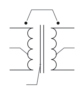
- 1 Dots
- Transformer dots mark corresponding voltage polarity: each dotted terminal has the same instantaneous polarity relative to its own winding's undotted terminal. The dots do not indicate equal voltage or current direction.Source 2
- 2 Primary winding
- As in the terminal key.
- 3 Secondary winding
- As in the terminal key.
-
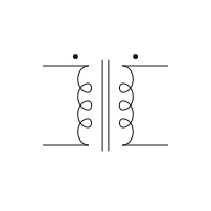
0°
-
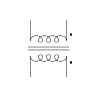
90°
-
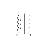
180°
-
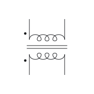
270°
-
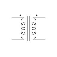
Mirrored
Rotating or mirroring a whole symbol, with its terminal identities and connections preserved, does not change the component. The terminal labels move with the drawing.Source 5
-
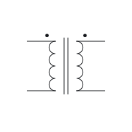
0°
-
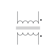
90°
-

180°
-
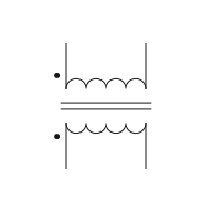
270°
-
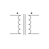
Mirrored
Rotating or mirroring a whole symbol, with its terminal identities and connections preserved, does not change the component. The terminal labels move with the drawing.Source 5
Variants
Often confused with
-
-
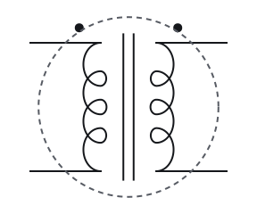
Transformer
Two or more windings facing each other
-
Inductor
Single winding
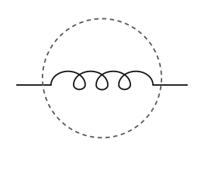
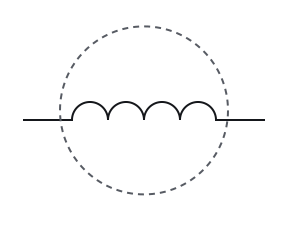
A transformer has two or more windings drawn facing each other, with core lines between them when it has a magnetic core. An inductor is a single winding with two terminals.Source 1Source 2Source 3
-
Transformer
Two or more windings facing each other
-
Inductor
Single winding
A transformer has two or more windings drawn facing each other, with core lines between them when it has a magnetic core. An inductor is a single winding with two terminals.Source 1Source 2Source 3
Fig. 4 — Transformer and inductor, the mark that tells them apart ringedTransformer and inductor, the mark that tells them apart ringed -
Where you meet it
Notes
An autotransformer shares one winding, so its sides are not isolated
An autotransformer is drawn as a single winding with taps rather than separate windings. Its primary and secondary connections share that winding, so there is no electrical isolation between them.Source 2 Every transformer on this sheet has separate windings, with no wire between them; the autotransformer is the exception to look for.
Loops and humps draw the same winding
Looped and semicircular coil drawings are alternative inductor forms. This sheet uses loops in its US view and humps in its IEC view; the winding and terminal roles are unchanged.Source 3 A single winding on its own is drawn the same way as an inductor; two windings facing each other, with or without core lines, make a transformer.
Check your reading
More questions on the practice pagePick an answer to see the reason.
Answer key
- 1
No: the windings are linked magnetically, not by a wire
- 2
It is the winding the source drives
- 3
Ends with the same polarity at the same instant
- 4
A centre tap
- 5
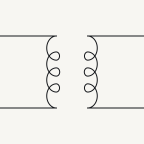
An air core: there is no magnetic core
Questions
- Which side of a transformer symbol is the primary?
- The winding the source drives, wherever it is drawn. Turning or mirroring the symbol does not change which winding is the primary and which the secondary.Source 1Source 5
- What is a centre tap on a transformer?
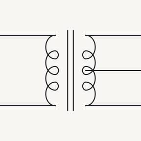
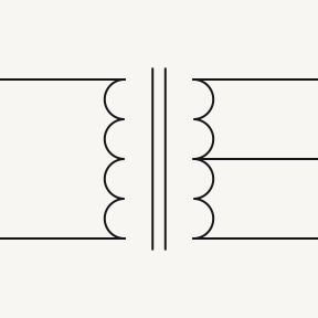
- A connection to the middle of a winding, drawn as an extra lead from that winding. Here it is labelled CT.Source 2Source 3
- What do the dots on a transformer symbol mean?
- They mark matching polarity. At any instant, each dotted end has the same polarity, measured against the other end of its own winding. They do not show equal voltages or which way current flows.Source 2
Print and files
Printable symbol sheetPrintable symbol sheet More worksheets
-
 US style PNG, 1200 × 900 SVG, line art
 -
 IEC style PNG, 1200 × 900 SVG, line art
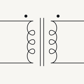
Variants as SVG line art: Centre-tapped transformerCentre-tapped transformer, Air-core transformerAir-core transformer
Sources
7 sources, numbered as cited
- ModEL — Components and Symbols, §§3.13–3.14 (inductors and transformers, pp. 24–26)
- ModEL — Transformers, §§4.1, 4.3–4.4 (windings, centre taps, autotransformers and dots)
- Lessons In Electric Circuits, Vol. V — §9, Circuit Schematic Symbols (pp. 130–139)
- Design to Manufacturing Standards — Reference Designators (slide 33)
- Electrical Schematics, §§1.3.1–1.3.5 — nodes, crossings, references and congruent drawings
- Chassis, Earth and Signal Grounding: Terminology and Symbols
- DC Electrical Circuit Analysis — resistive devices and schematic ground symbols (pp. 53, 59–64)