Capacitor symbol
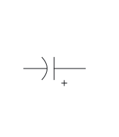
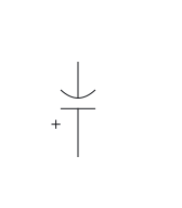
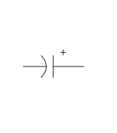
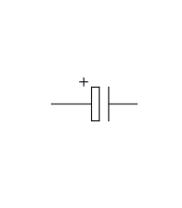
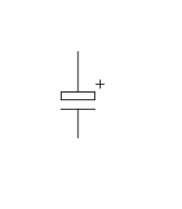
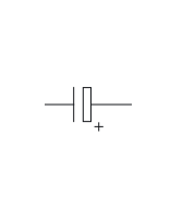
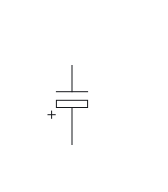
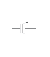
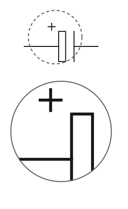
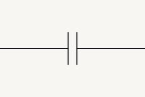
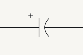
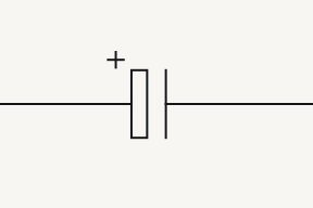
Two equal plates mean a capacitor with no polarity. A polarised capacitor, such as most electrolytics, adds a + mark. In the drawings here the curved US plate is negative and the hollow IEC plate is positive.Source 1Source 2Source 3Source 4Source 5Source 6Source 7Source 8
Symbol and terminals
Terminals
- 12
- A non-polarised capacitor has two interchangeable terminals.Source 1
Parts of the drawing
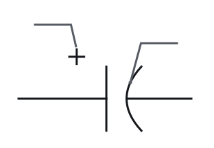
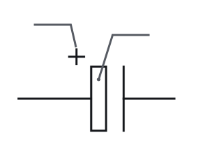
-
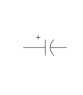
0°
-
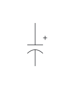
90°
-
180°
-
270°
-
Mirrored
Rotating or mirroring a whole symbol, with its terminal identities and connections preserved, does not change the component. The terminal labels move with the drawing.Source 10
-
0°
-
90°
-
180°
-
270°
-
Mirrored
Rotating or mirroring a whole symbol, with its terminal identities and connections preserved, does not change the component. The terminal labels move with the drawing.Source 10
Variants
Often confused with
-
-
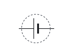
Cell
Lines differ in length
-
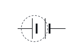
Battery
Lines differ in length
-
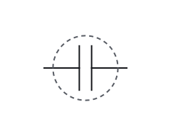
Capacitor
Two plates drawn the same length
-
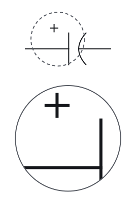
Polarised capacitor
Polarity mark
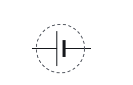
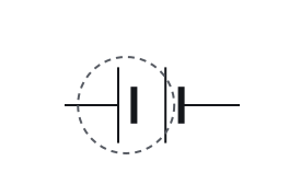
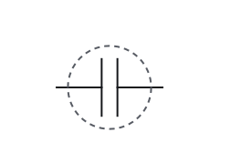
A cell and a capacitor are both drawn as two parallel lines. In a cell, and in each cell of a battery, the lines differ in length and the long line is the positive terminal; a capacitor's two plates are drawn the same length, and only a polarised capacitor adds a polarity mark.Source 1Source 2Source 3Source 4
-
Cell
Lines differ in length
-
Battery
Lines differ in length
-
Capacitor
Two plates drawn the same length
-
Polarised capacitor
Polarity mark
A cell and a capacitor are both drawn as two parallel lines. In a cell, and in each cell of a battery, the lines differ in length and the long line is the positive terminal; a capacitor's two plates are drawn the same length, and only a polarised capacitor adds a polarity mark.Source 1Source 2Source 3Source 4
Fig. 4 — Cell, battery, capacitor and polarised capacitor, the mark that tells them apart ringedCell, battery, capacitor and polarised capacitor, the mark that tells them apart ringed -
-
-
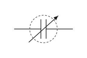
Variable capacitor
Plates
-
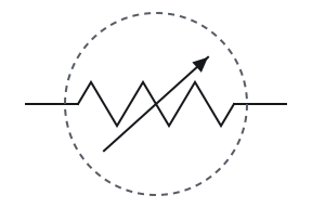
Variable resistor
Zigzag
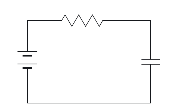
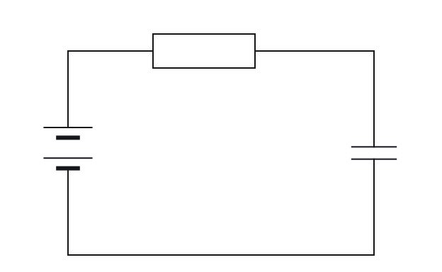
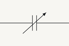
A diagonal arrow through a symbol marks it as adjustable, whatever the component, so the body under the arrow says what it is: plates for a variable capacitor, a zigzag or rectangle for a variable resistor, a coil for a variable inductor.Source 3Source 4
-
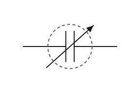
Variable capacitor
Plates
-
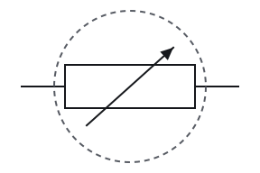
Variable resistor
Rectangle
A diagonal arrow through a symbol marks it as adjustable, whatever the component, so the body under the arrow says what it is: plates for a variable capacitor, a zigzag or rectangle for a variable resistor, a coil for a variable inductor.Source 3Source 4
Fig. 5 — Variable capacitor and variable resistor, the mark that tells them apart ringedVariable capacitor and variable resistor, the mark that tells them apart ringed -
On the part
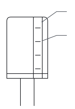
- 1 Stripe
- 2 − sign
- Many electrolytic capacitors are marked for polarity on the part itself, typically with a − sign beside the negative lead, often printed on a stripe down the can. That marking belongs to the part, not the schematic, and it is not uniform: some parts mark the positive terminal instead, and a stripe on a non-polarised film capacitor means something else.Source 7Source 11
Where you meet it
Notes
Most electrolytics are polarised, but not all
Most electrolytic capacitors are polarised: voltage of the wrong polarity can damage their very thin oxide insulating layer, so they are marked to show their polarity. The two words are not interchangeable, since non-polarised electrolytic capacitors also exist and are usually marked NP.Source 5Source 6Source 7 A polarised part is drawn with the polarised capacitor symbol, whose + names the terminal to keep the more positive.
The + names a terminal; the part’s own marking finds the lead
A capacitor's + mark identifies its positive electrical terminal. A schematic does not specify physical lead length or package pinout; those require the component's own markings and documentation.Source 1Source 10Source 12 The band on a diode works the same way, as the diode symbol page explains for the cathode.
2p2 is 2.2 pF, and 2n2 is 2.2 nF
Capacitor values use the same idea with p and n: 2p2 is 2.2 pF and 2n2 is 2.2 nF. Some makers write R instead on a capacitor, where 2R2 means 2.2 pF rather than 2.2 Ω.Source 13Source 14 Resistor values follow the same letter code: on the resistor symbol page, 4k7 is 4.7 kΩ.
Check your reading
More questions on the practice pagePick an answer to see the reason.
Answer key
- 1
A capacitor
- 2
Its capacitance can be adjusted
- 3
Yes: the curved plate and the + mark it
- 4
No: read the marking on the part itself
- 5
The positive plate
Questions
Print and files
Printable symbol sheetPrintable symbol sheet More worksheets
-
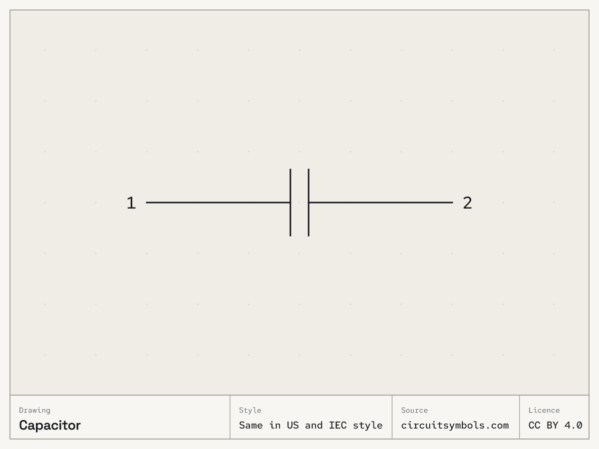 Same in US and IEC style PNG, 1200 × 900 SVG, line art
Variants as SVG line art: Polarised (polarized) capacitorPolarised (polarized) capacitor, Variable capacitor
Sources
16 sources, numbered as cited
- ModEL — Components and Symbols, §3.15 (capacitor polarity, pp. 27–28)
- ModEL — Components and Symbols, §3.5 (cells and ideal source symbols, p. 12)
- DC Electrical Circuit Analysis — resistive devices and schematic ground symbols (pp. 53, 59–64)
- Lessons In Electric Circuits, Vol. V — §9, Circuit Schematic Symbols (pp. 130–139)
- ModEL — Capacitors and Capacitive Circuits, §3.6 (electrolytic capacitors, p. 53)
- ECE 2210 Capacitors Lab — electrolytic capacitors (p. 2)
- Capacitor Codes (seminar handout)
- University Physics, Vol. 2, §8.1 — capacitor representations, Figure 8.9
- Design to Manufacturing Standards — Reference Designators (slide 33)
- Electrical Schematics, §§1.3.1–1.3.5 — nodes, crossings, references and congruent drawings
- ModEL — Capacitors and Capacitive Circuits, §5.2 (capacitor labelling and polarity stripes, pp. 70–72)
- General Descriptions of Aluminum Electrolytic Capacitors — reverse polarity, §2-3-2
- ModEL — Components and Symbols, §4.3 (capacitor labelling, p. 49)
- IEC 60062:2016+AMD1:2019 — Marking codes for resistors and capacitors; public preview contents (preview p. 3)
- ModEL — Semiconductor Logic Gates, §2.1 (schematic versus package pinout, p. 8)
- ModEL — Electromechanical Relays, §§3.2–3.3 and §5.1 (normal and present contact status)