How to read a schematic
A schematic shows how parts connect, not where they sit. Wire that runs unbroken is one node. A dot or a T joins wires; in the convention used here a plain crossing does not. Letters such as R1 name the parts.Source 1Source 2Source 3Source 4
On this sheet
Trace a node
Choose a node, or tap a wire in the drawing. Every conductor on that node lights up.
Circuit 1 Torch
No node selected.
Node 1: Cell positive to switch. Joins BT1 + and S1 terminal 1.
Node 2: Switch to lamp. Joins S1 terminal 2 and DS1 terminal 1.
Node 3: Lamp back to cell negative. Joins DS1 terminal 2 and BT1 −.
Parts
Questions on Fig. 1
-
Is the switch's right-hand terminal on the same node as the lamp's upper terminal?
-
How many nodes does this circuit have?
Four reading rules
-
1 Designators and values
Reference designators identify parts with class letters and a number. Common letters used here are R resistor, C capacitor, D diode, Q transistor, L inductor, T transformer, S switch, K relay and F fuse; other naming systems exist.Source 4
Values printed beside a symbol may put the multiplier letter where the decimal point would be: 4k7 means 4.7 kΩ, 3R9 means 3.9 Ω, 47R means 47 Ω and 2M2 means 2.2 MΩ. IEC 60062 sets out this letter code.Source 5Source 6Source 7
Capacitor values use the same idea with p and n: 2p2 is 2.2 pF and 2n2 is 2.2 nF. Some makers write R instead on a capacitor, where 2R2 means 2.2 pF rather than 2.2 Ω.Source 7Source 8
A reading aid only; this site gives no advice on choosing values.
R14k7C12n2K1R14k7C12n2K1Fig. 2 — Designators and printed values: R1 marked 4k7, C1 marked 2n2, and relay K1 -
2 Junctions and crossings
In the drawing convention used here, a dot marks a wire connection and a plain four-way crossing without a dot is not connected. Older drawings may use another convention, so check their legend.Source 1Source 3
Wires that meet in a T are connected whether or not a dot is drawn there. Where four wires cross and connect, the dot is what shows it.Source 1
A small half-circle hop where one wire passes over another also means the wires are not connected. Some drawings put a hop at every unconnected crossing and a dot at every connection, so neither is left to guess.Source 1Source 3Source 9
JoinedDotT, dotT, no dotNot joinedNo dotHopFig. 3 — Five ways wires meet or cross -
3 Nodes
In the ideal-wire schematic model, a node is the set of points connected by uninterrupted wire. Those points share one potential; real wire resistance and other wire effects are omitted.Source 1Source 2
BT1S1DS1Node 2BT1S1DS1Node 2Fig. 4 — The torch from Fig. 1 with Node 2 drawn heavy: S1 terminal 2, DS1 terminal 1 and the wire between them -
4 Rails and references
Within the drawing's stated scope, repeated supply or reference labels identify the same node without a drawn wire between them. Different labels or reference symbols must not be assumed connected.Source 1
A supply connection is often drawn as a short labelled stub or dot, such as +5 V, VCC or VDD, instead of a wire back to the source. The source's other side is taken to be the ground reference, and every stub with the same label is the same node.Source 1Source 5Source 10
A label such as GND, Gnd or 0 V at a reference symbol names the node that other potentials are measured from. A drawing may keep separate commons, such as an analog signal common and a digital logic common, so differently named references must not be assumed to be joined.Source 1Source 2Source 5
+5 V+5 VSame label: one node0 V0 VSame label: one node0 VEarthDifferent references: not assumed joinedFig. 5 — Two +5 V supply stubs, two 0 V reference marks, then a 0 V mark beside an earth mark
Five more circuits
Each one practises the rules above. Pick a circuit, trace it, then answer its questions.
Circuit 2 Series chain
No node selected.
Node 1: Cell positive to R1 terminal 1. Joins BT1 + and R1 terminal 1.
Node 2: R1 terminal 2 to R2 terminal 1. Joins R1 terminal 2 and R2 terminal 1.
Node 3: R2 terminal 2 to lamp terminal 2. Joins R2 terminal 2 and DS1 terminal 2.
Node 4: Lamp terminal 1 back to cell negative. Joins DS1 terminal 1 and BT1 −.
Parts
Questions on Fig. 6
-
Which node joins R1 to R2?
-
Are the cell negative terminal and the lower terminal of R2 on the same wire node, or is DS1 between them?
Circuit 3 Parallel branches
No node selected.
Node 1: Upper rail: cell positive and both resistor terminal 1 connections. Joins BT1 +, R1 terminal 1 and R2 terminal 1.
Node 2: Lower rail: cell negative and both resistor terminal 2 connections. Joins BT1 −, R1 terminal 2 and R2 terminal 2.
Parts
- BT1
- Cell
Questions on Fig. 7
-
Do both upper resistor terminals share a node?
-
At each junction dot, which three conductor directions meet?
Circuit 4 Crossing paths
No node selected.
Node 1: Left continuation to R1 terminal 1. Joins R1 terminal 1.
Node 2: Horizontal link from R1 terminal 2 to R2 terminal 1. Joins R1 terminal 2 and R2 terminal 1.
Node 3: R2 terminal 2 to the right continuation. Joins R2 terminal 2.
Node 4: Upper continuation to C1 terminal 1. Joins C1 terminal 1.
Node 5: C1 terminal 2 to the lower continuation. Joins C1 terminal 2.
Parts
Questions on Fig. 8
-
Does the horizontal resistor link join the upper capacitor lead at the crossing?
Check the answer
No. The vertical wire crosses the link with no dot, so R1 terminal 2 and C1 terminal 1 stay on different nodes. Source 3
-
Which two resistor terminals share the horizontal link node?
Check the answer
R1 terminal 2 and R2 terminal 1. The wire that crosses the link has no dot there, so it adds nothing to that node. Source 3
Circuit 5 Labelled return
No node selected.
Node 1: Cell positive to R1 terminal 1. Joins BT1 + and R1 terminal 1.
Node 2: Shared signal-reference node: cell negative, R1 terminal 2 and both REF marks. Joins BT1 −, left REF mark, R1 terminal 2 and right REF mark.
Questions on Fig. 9
-
Which two separated drawing fragments belong to REF?
Check the answer
The left fragment, the cell's − terminal with the REF mark under it, and the right fragment, the wire from R1 terminal 2 down to the second REF mark. The repeated REF label makes them one node. Source 1
-
Do the cell negative terminal and R1 terminal 2 share a node even though no return wire is drawn between the REF marks?
Check the answer
Yes. Both marks carry the same REF label, so the drawing treats them as one node without a drawn wire between them. Source 1
Circuit 6 Relay separation
No node selected.
Node 1: BT1 positive to relay coil A1. Joins BT1 + and K1 A1.
Node 2: Relay coil A2 to BT1 negative. Joins K1 A2 and BT1 −.
Node 3: BT2 positive to R1 terminal 1. Joins BT2 + and R1 terminal 1.
Node 4: R1 terminal 2 to relay NC. Joins R1 terminal 2 and K1 NC.
Node 5: Relay COM to BT2 negative. Joins K1 COM and BT2 −.
Node 6: Relay NO continuation without another component. Joins K1 NO.
Questions on Fig. 10
-
Which two external wire nodes touch coil terminals A1 and A2?
-
Does any contact-side conductor join a coil-side conductor?
-
Which contact terminal ends without another component attached in this drawing?
Every convention on one drawing
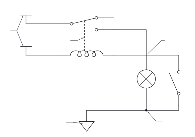
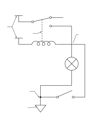
- 1 Reference designators
- As in rule 1.
- 2 Short labelled stub
- As in rule 4.
- 3 Dashed line
- A dashed line joining parts of a symbol shows a mechanical link: the parts move together, but the line is not a wire and carries no current.Source 9Source 13
- 4 Cross with no dot
- In the newer convention used here, wires that cross with no dot are not connected. Older schematics drew connected wires as a plain crossing and made unconnected wires hop over each other with a small half-circle, so check a drawing's legend.Source 3
- 5 Signal-reference symbol
- The signal-reference symbol marks the chosen zero-volt reference for circuit voltages. It need not be connected to earth or chassis.Source 1Source 14
- 6 0 V
- As in rule 4.
- 7 Dot
- As in rule 2.
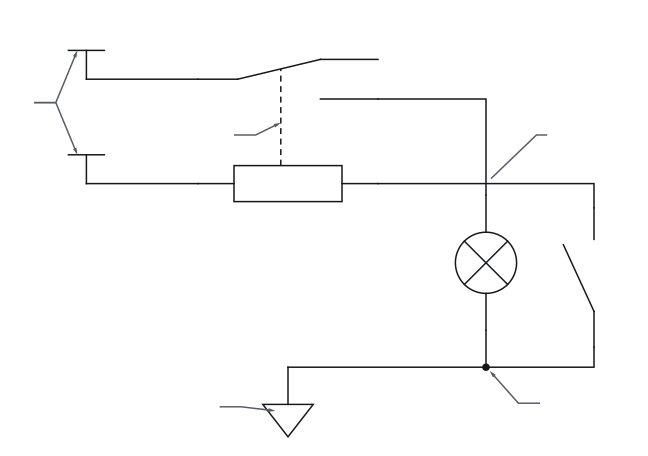
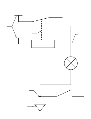
- 1 Reference designators
- As in rule 1.
- 2 Short labelled stub
- As in rule 4.
- 3 Dashed line
- A dashed line joining parts of a symbol shows a mechanical link: the parts move together, but the line is not a wire and carries no current.Source 9Source 13
- 4 Cross with no dot
- In the newer convention used here, wires that cross with no dot are not connected. Older schematics drew connected wires as a plain crossing and made unconnected wires hop over each other with a small half-circle, so check a drawing's legend.Source 3
- 5 Signal-reference symbol
- The signal-reference symbol marks the chosen zero-volt reference for circuit voltages. It need not be connected to earth or chassis.Source 1Source 14
- 6 0 V
- As in rule 4.
- 7 Dot
- As in rule 2.
Notes
- A schematic describes electrical connections only, not where parts sit. Parts can be moved or redrawn anywhere on the page without changing the circuit, as long as every connection is kept.Source 1
- NC has two unrelated meanings. At a switch or relay contact it means normally closed; on an integrated-circuit pin diagram, nc marks a pin that is not connected.Source 11Source 15
Check your reading
More questions on the practice pagePick an answer to see the reason.
Answer key
- 1
No: the switch and the lamp sit between them
- 2
No: without a dot they are not connected
- 3
A relay
- 4
Yes: stubs with the same label are one node
- 5
4.7 kΩ
Questions
- Do crossing wires connect?
- Not where they cross without a dot. A dot joins them, and wires that meet in a T are joined with or without one. Older drawings may follow another rule, some using a small hop for wires that do not connect, so check the legend.Source 1Source 3Source 9
- What does R1 or K1 mean?
- It is a reference designator: the letters give the kind of part and the number tells parts of that kind apart. R is a resistor and K a relay.Source 4
Sources
15 sources, numbered as cited
- Electrical Schematics, §§1.3.1–1.3.5 — nodes, crossings, references and congruent drawings
- ModEL — Sources and Loads, Voltmeters and Ammeters, §§4.2–4.6 and §6.2
- Lessons In Electric Circuits, Vol. V — §9, Circuit Schematic Symbols (pp. 130–139)
- Design to Manufacturing Standards — Reference Designators (slide 33)
- DC Electrical Circuit Analysis — resistive devices and schematic ground symbols (pp. 53, 59–64)
- ModEL — Ohm’s and Joule’s Laws, Resistor Ratings, and Electrical Safety, §6.2 (resistor labelling, p. 73)
- IEC 60062:2016+AMD1:2019 — Marking codes for resistors and capacitors; public preview contents (preview p. 3)
- ModEL — Components and Symbols, §4.3 (capacitor labelling, p. 49)
- ModEL — Components and Symbols, §3.20 (wire crossings and dashed links, p. 36)
- ModEL — Semiconductor Logic Gates, §3.4 (supply terminal labels VCC, VEE, VDD and VSS, p. 43)
- ModEL — Electromechanical Relays, §§3.2–3.3 and §5.1 (normal and present contact status)
- Relay technology — structure, operation and contact forms
- ModEL — Components and Symbols, §3.8 (switch symbols, poles, throws and dashed links, pp. 15–16)
- Where Is Ground? — local reference versus earth
- Lessons In Electric Circuits, Vol. IV — §12, shift-register pin diagram (nc pins, p. 356)