Relay symbol
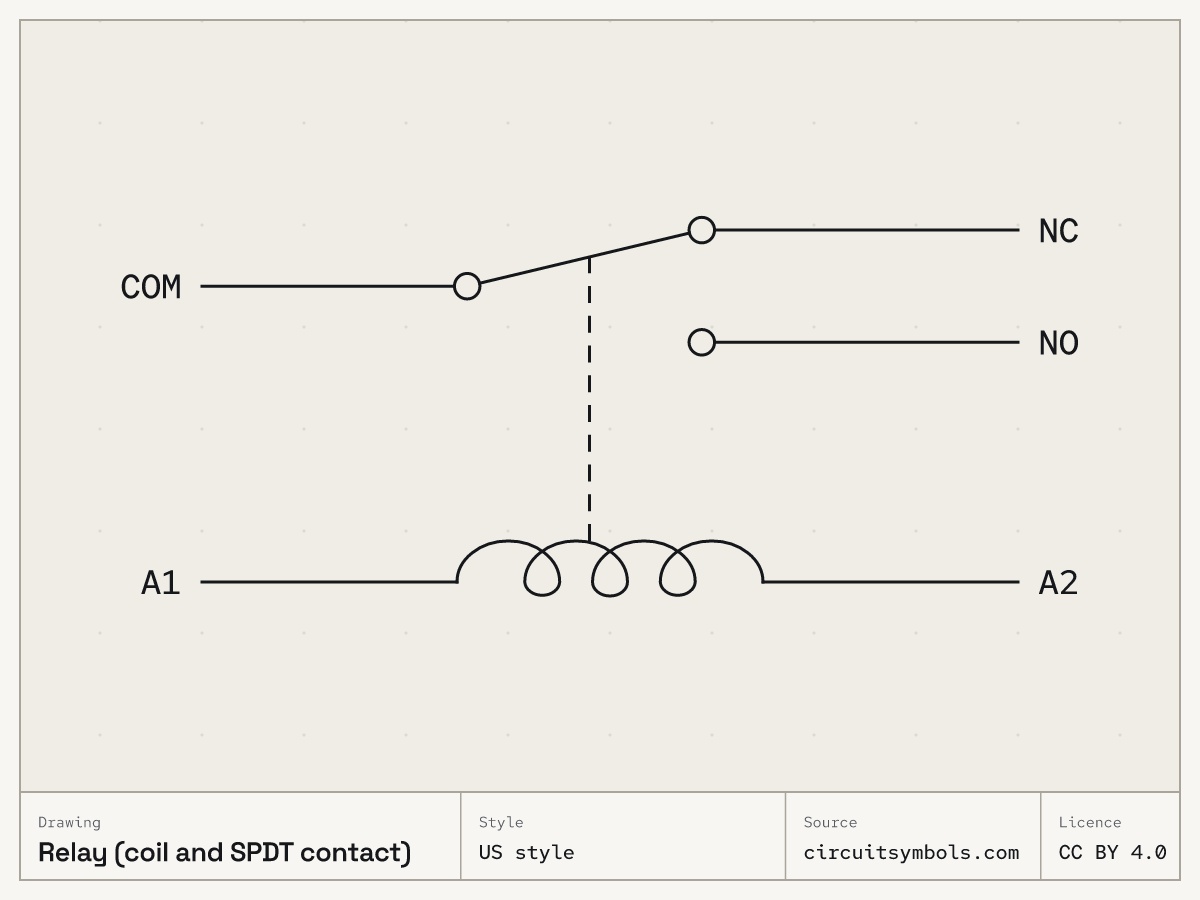
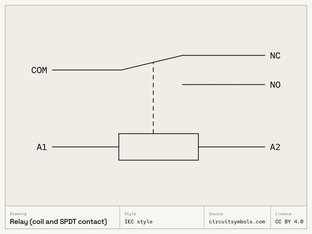
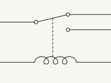
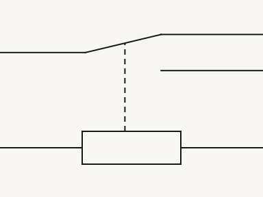
A relay symbol pairs a coil with the contacts it moves. In the relay drawn here the contacts are at rest, with the coil de-energised: COM on NC. Energise the coil and COM moves to NO; the printed symbol and its labels do not change.Source 1Source 2Source 3Source 4
Symbol and what it is doing
US style
IEC style
Energise the coil. The contact drawn in ink stays at rest; the highlight shows which pair is joined now.
COM–NC conducts. Under the single-stable relay model, the coil is de-energised and settled: COM–NC is closed and COM–NO is open. This is the drawn resting state.
COM–NO conducts. Under the single-stable relay model, the coil is energised and settled: COM–NO is closed and COM–NC is open. The printed contact stays at rest; only the highlight shows the present position.
In the single-stable changeover relay shown here, energising the coil transfers COM from NC to NO after the operating delay. The printed symbol and its NO/NC labels remain unchanged.
Terminals
- COM
- COM is the common contact, the one the moving arm belongs to.Source 1
- NC
- NC is the normally-closed contact: it is connected to COM in the resting, de-energised state of the single-stable relay shown here.Source 1Source 3Source 6
- NO
- NO is the normally-open contact: it is disconnected from COM at rest and connected after the coil has energised the single-stable relay shown here.Source 1
- A1A2
- The two coil terminals are the control side of the relay; the current that flows through them moves the contacts.Source 1
Parts of the drawing
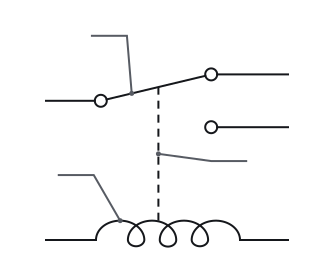
- 1 Resting position
- For the non-latching relay shown here, normal means the coil is de-energised. NO contacts are drawn open and NC contacts closed; these labels describe their resting positions.Source 1Source 3Source 4
- 2 Coil
- A relay symbol combines a coil with the contacts it moves, joined by a dashed mechanical link. US drawings show the coil as loops and IEC drawings as a rectangle; a plain switch has no coil.Source 3Source 4
- 3 Mechanical link
- The dashed line between coil and contact is the mechanical link; it carries no current.Source 1
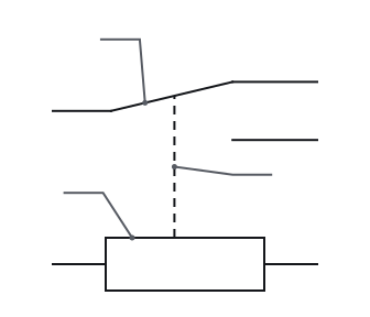
- 1 Resting position
- For the non-latching relay shown here, normal means the coil is de-energised. NO contacts are drawn open and NC contacts closed; these labels describe their resting positions.Source 1Source 3Source 4
- 2 Coil
- A relay symbol combines a coil with the contacts it moves, joined by a dashed mechanical link. US drawings show the coil as loops and IEC drawings as a rectangle; a plain switch has no coil.Source 3Source 4
- 3 Mechanical link
- The dashed line between coil and contact is the mechanical link; it carries no current.Source 1
-
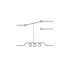
0°
-
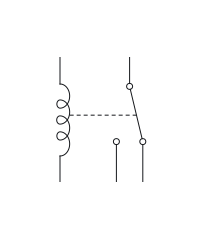
90°
-
180°
-
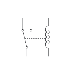
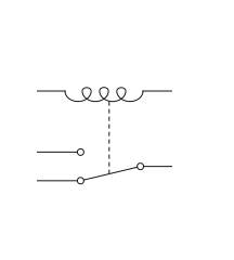
270°
-
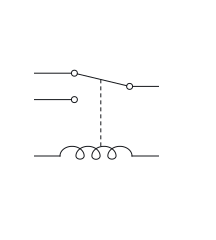
Mirrored
Rotating or mirroring a whole symbol, with its terminal identities and connections preserved, does not change the component. The terminal labels move with the drawing.Source 7
-
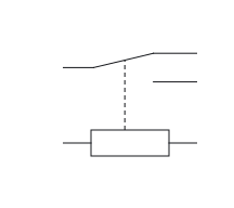
0°
-
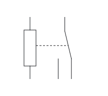
90°
-
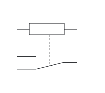
180°
-
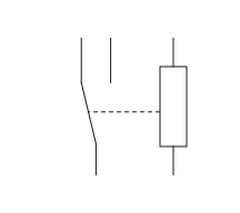
270°
-
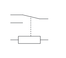
Mirrored
Rotating or mirroring a whole symbol, with its terminal identities and connections preserved, does not change the component. The terminal labels move with the drawing.Source 7
Often confused with
-
-
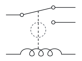
Relay (coil and SPDT contact)
Dashed mechanical link
-
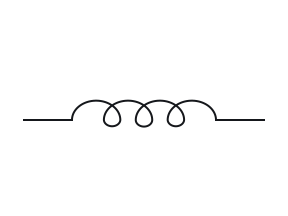
Inductor
-
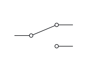
Switch (SPDT)
No coil
-
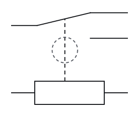
Relay (coil and SPDT contact)
Dashed mechanical link
-
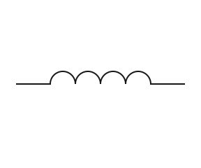
Inductor
-
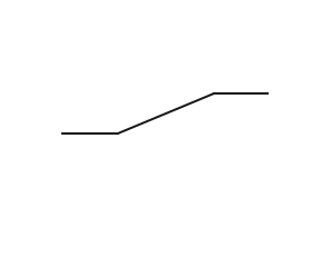
Switch (SPDT)
No coil
Fig. 4 — Relay (coil and SPDT contact), inductor and switch (SPDT), the mark that tells them apart ringedRelay (coil and SPDT contact), inductor and switch (SPDT), the mark that tells them apart ringed The sentence that tells these apart is in Fig. 2, the parts of the drawing.
-
Poles and throws
| Single throw | Double throw | |
|---|---|---|
| Single pole | 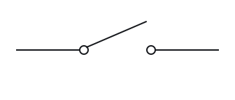 SPST 2 contact terminals | 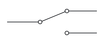 SPDT 3 contact terminals |
| Double pole | 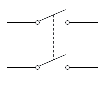 DPST 4 contact terminals | 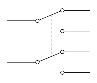 DPDT 6 contact terminals |
Each pole has a common terminal plus one terminal for each throw. So an SPST switch has 2 contact terminals, SPDT 3, DPST 4 and DPDT 6.Source 1Source 8
| Single throw | Double throw | |
|---|---|---|
| Single pole | 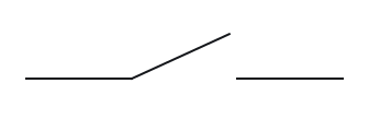 SPST 2 contact terminals | 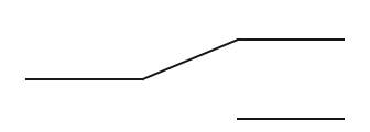 SPDT 3 contact terminals |
| Double pole | 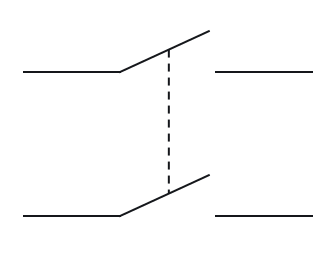 DPST 4 contact terminals | 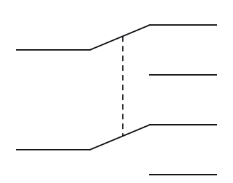 DPDT 6 contact terminals |
Each pole has a common terminal plus one terminal for each throw. So an SPST switch has 2 contact terminals, SPDT 3, DPST 4 and DPDT 6.Source 1Source 8
Notes
The contact drawn here is Form C, a changeover
Form A is another name for a normally-open contact and Form B for a normally-closed one. A single-pole, double-throw contact that has both, sharing a common terminal, is called Form C or a changeover contact.Source 1Source 8 A DPDT relay has two Form C contact sets moved together by one coil. The two poles are electrically isolated from each other, so each can switch a separate circuit.Source 1Source 3 The switch symbol page draws the same forms as hand-worked switches, with the common terminal on the moving arm there too.
A latching relay is drawn in its reset state
A latching relay has no spring-return resting position: it stays in its last position until its coil is signalled again. Its contacts are drawn in the reset state, as a single-stable relay's contacts are drawn at rest.Source 9 The cases on this sheet model the single-stable relay only.
The relay’s own diagram says which number is which
Terminal numbers are printed names, not part of the symbol: relays from different makers can number the same common, normally-open and normally-closed contacts differently. A relay's own diagram says which number is which.Source 1Source 10 The IEC-style 11, 12 and 14 and the automotive 30, 87 and 87a are common schemes, and a given relay may follow either one or neither.
NC can also mean not connected
NC has two unrelated meanings. At a switch or relay contact it means normally closed; on an integrated-circuit pin diagram, nc marks a pin that is not connected.Source 1Source 11 Beside a relay contact, read NC as normally closed, the partner of normally open.
Check your reading
More questions on the practice pagePick an answer to see the reason.
Answer key
- 1
COM and NC
COMNCNOA1A2COMNCNOA1A2 - 2
Nothing: they name the resting positions
- 3
COM
- 4
No current: it is a mechanical link
- 5
30
Questions
- What do NO and NC mean on a relay?
- Normally open and normally closed, where normally means with the coil de-energised. At rest NC is joined to COM and NO is not; once the coil is energised, COM joins NO.Source 1Source 3Source 6
- What do 11, 12, 14, A1 and A2 mean on a relay?
- They are IEC-style terminal names. A1 and A2 are the coil. Contact terminals have two digits: the first counts the contact set and the second gives its function, so 11 is common, 12 normally closed and 14 normally open.Source 10Source 12Source 13Source 14
Print and files
Sources
17 sources, numbered as cited
- ModEL — Electromechanical Relays, §§3.2–3.3 and §5.1 (normal and present contact status)
- Relay technology — structure, operation and contact forms
- ModEL — Components and Symbols, §3.11 (relay symbol, p. 21)
- ModEL — Components and Symbols, §3.8 (switch symbols, poles, throws and dashed links, pp. 15–16)
- Design to Manufacturing Standards — Reference Designators (slide 33)
- AT121 course notes — Relays: ISO relay contact numbers
- Electrical Schematics, §§1.3.1–1.3.5 — nodes, crossings, references and congruent drawings
- ModEL — Electrical Switches, §§3.1–3.3 (pp. 16–19)
- ModEL — Electromechanical Relays, §3.7 (latching relays, p. 41)
- Info Byte: What’s the Reason Behind Relay Terminal Numbering? (23 February 2022)
- Lessons In Electric Circuits, Vol. IV — §12, shift-register pin diagram (nc pins, p. 356)
- ModEL — AC Induction Motor Starters, §2.1 (contactor coil terminals A1 and A2, pp. 7–9)
- Motor Branch Circuits Basics, IEC & NEMA Devices — numbers on IEC relay terminals (slides 17 and 24)
- IEC 60947-5-1:2024 — control circuit devices; public preview contents, Annex M (preview p. 6)
- Electromechanical: Switches and Relays (30 May 2024)
- DIN 72552-2:2014-07 — Terminal markings for vehicles, Part 2: Codes (status page)
- ModEL — Components and Symbols, §3.20 (wire crossings and dashed links, p. 36)