Circuit Symbols
Drawing style

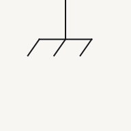
Ground symbol

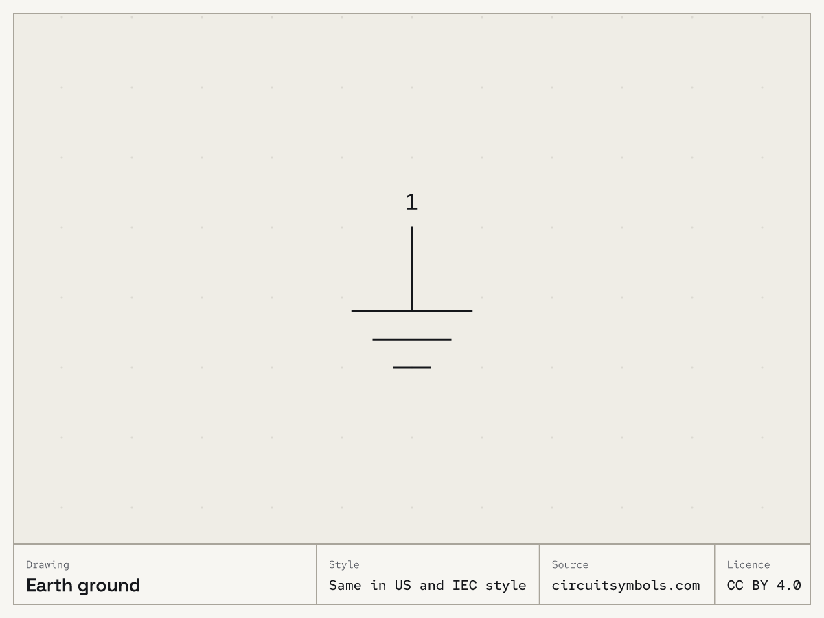
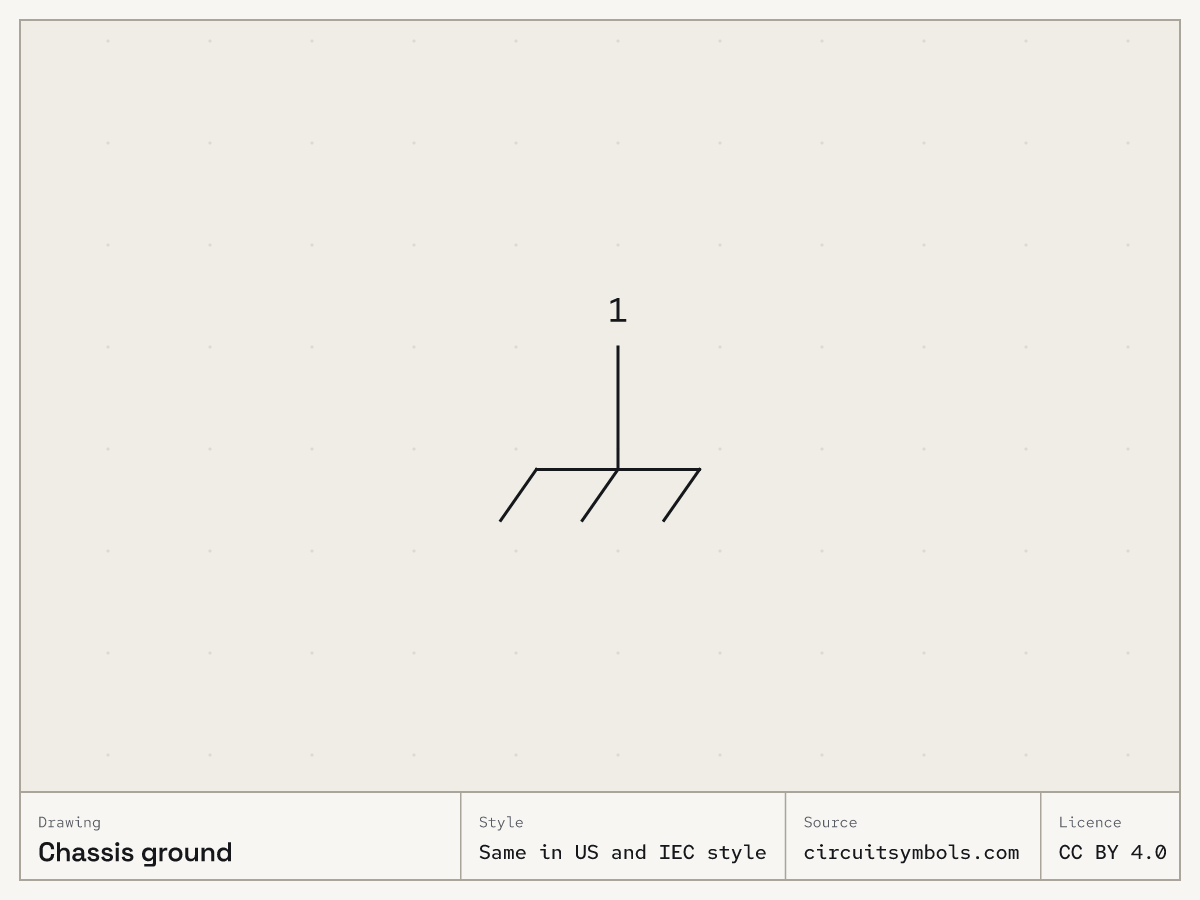
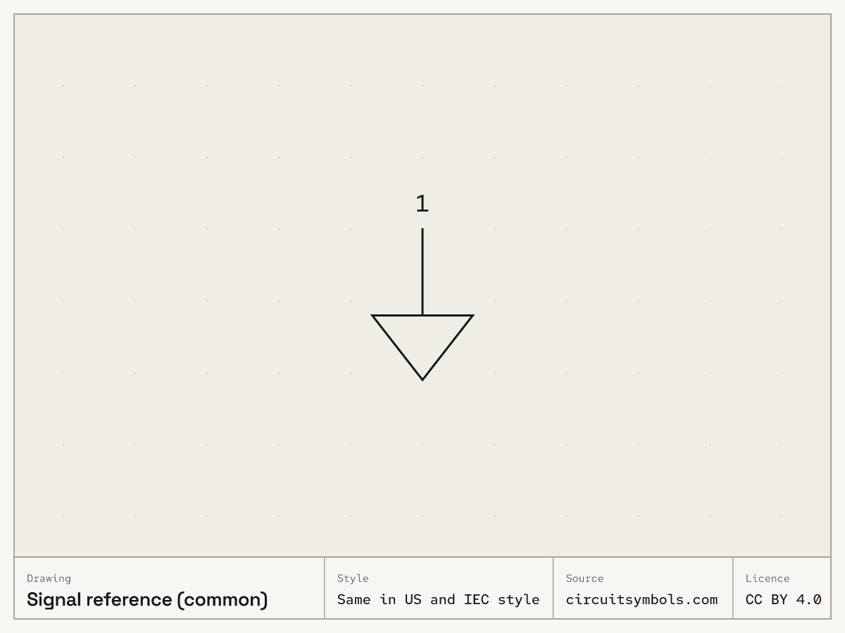
Three different things get called ground. In the drawings here, shortening horizontal lines mark earth, a hatched line marks the equipment chassis, and an open triangle marks the circuit's 0 V signal reference, which need not connect to earth.⁠Source 1Source 2Source 3Source 4

On this sheet

Three reference symbols

Earth ground

Chassis ground

Signal reference (common)

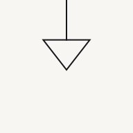
Fig. 1 — Earth ground, chassis ground and signal reference (common), drawn the same in US and IEC style; terminal 1 on each

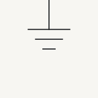
The three reference marks differ in shape: earth is three horizontal lines getting shorter, chassis is a line with slanted strokes below it, and the signal reference is an open triangle pointing down.⁠Source 1Source 2

Earth ground, Chassis ground, Signal reference (common) compared
Earth groundChassis groundSignal reference (common)
What it marks In the convention used here, three horizontal lines of decreasing length identify a connection to earth. Check a drawing's legend: the same shape is sometimes used more generally for circuit ground.⁠Source 1Source 2The chassis symbol (hatched) marks a connection to the equipment's metal frame or enclosure.⁠Source 1Source 2The signal-reference symbol marks the chosen zero-volt reference for circuit voltages. It need not be connected to earth or chassis.⁠Source 3Source 4
Connection point Each ground or reference symbol shown here has one connection point to the circuit; it identifies a reference connection, not a two-terminal component.⁠Source 2
Reference designator A ground or reference symbol marks a connection to the circuit's common reference, not a part, so the drawings here give it no reference designator. A label such as GND or 0 V names that node instead.⁠Source 2Source 5Source 6
Labels you may see beside it A label such as GND, Gnd or 0 V at a reference symbol names the node that other potentials are measured from. A drawing may keep separate commons, such as an analog signal common and a digital logic common, so differently named references must not be assumed to be joined.⁠Source 2Source 4Source 5
Joined to the others on the drawing? Within the drawing's stated scope, repeated supply or reference labels identify the same node without a drawn wire between them. Different labels or reference symbols must not be assumed connected.⁠Source 4

Notes

A labelled supply stub stands in for a wire back to the source

A supply connection is often drawn as a short labelled stub or dot, such as +5 V, VCC or VDD, instead of a wire back to the source. The source's other side is taken to be the ground reference, and every stub with the same label is the same node.⁠Source 2Source 4Source 7 That is why a sheet can show +5 V at the top and a reference symbol at the bottom, with nothing drawn to join either one to the battery.

Every point joined to the reference shares its potential

In the ideal-wire schematic model, a node is the set of points connected by uninterrupted wire. Those points share one potential; real wire resistance and other wire effects are omitted.⁠Source 4Source 5 A reference symbol names one such node, the signal reference, and the tracer on how to read a schematic follows one through a whole circuit.

Pick an answer to see the reason.

  1. Question 1

    Which kind of reference does this mark stand for?

    A vertical lead ending in three horizontal lines, one under another, each shorter than the one above it.

    Not this one Right Answer

    The answer is “Earth”. The three reference marks differ in shape: earth is three horizontal lines getting shorter, chassis is a line with slanted strokes below it, and the signal reference is an open triangle pointing down.The chassis symbol (hatched) marks a connection to the equipment's metal frame or enclosure. In the convention used here, three horizontal lines of decreasing length identify a connection to earth. Check a drawing's legend: the same shape is sometimes used more generally for circuit ground.

  2. Question 2

    What is this reference mark connected to?

    A vertical lead ending in a horizontal line with three short slanted strokes hanging below it.

    Not this one Right Answer

    The answer is “The equipment's metal frame or enclosure”. This sheet distinguishes earth, chassis and signal reference. They can be connected in a circuit, but the three labels have different meanings; ground does not always mean a connection to earth.The three reference marks differ in shape: earth is three horizontal lines getting shorter, chassis is a line with slanted strokes below it, and the signal reference is an open triangle pointing down. The chassis symbol (hatched) marks a connection to the equipment's metal frame or enclosure.

  3. Question 3

    Does this reference mark, on its own, connect the circuit to earth?

    A vertical lead ending in an open triangle that points down.

    Not this one Right Answer

    The answer is “No: it marks the circuit's 0 V reference”. This sheet distinguishes earth, chassis and signal reference. They can be connected in a circuit, but the three labels have different meanings; ground does not always mean a connection to earth.A label such as GND, Gnd or 0 V at a reference symbol names the node that other potentials are measured from. A drawing may keep separate commons, such as an analog signal common and a digital logic common, so differently named references must not be assumed to be joined. The signal-reference symbol marks the chosen zero-volt reference for circuit voltages. It need not be connected to earth or chassis.

  4. Question 4

    On one sheet, a reference symbol labelled AGND marks the analog common and another labelled DGND marks the digital common. No wire is drawn between them. Are they one node?

    Not this one Right Answer

    The answer is “No: references with different names are not assumed joined”. Within the drawing's stated scope, repeated supply or reference labels identify the same node without a drawn wire between them. Different labels or reference symbols must not be assumed connected.Within the drawing's stated scope, repeated supply or reference labels identify the same node without a drawn wire between them. Different labels or reference symbols must not be assumed connected. A label such as GND, Gnd or 0 V at a reference symbol names the node that other potentials are measured from. A drawing may keep separate commons, such as an analog signal common and a digital logic common, so differently named references must not be assumed to be joined.

  5. Question 5

    How many connections does this earth symbol make to the circuit?

    A lead coming in from the right and ending in three vertical lines side by side, each shorter than the one before as they go left.

    Not this one Right Answer

    The answer is “One, at the end of its lead”. The three reference marks differ in shape: earth is three horizontal lines getting shorter, chassis is a line with slanted strokes below it, and the signal reference is an open triangle pointing down.A ground or reference symbol marks a connection to the circuit's common reference, not a part, so the drawings here give it no reference designator. A label such as GND or 0 V names that node instead. Each ground or reference symbol shown here has one connection point to the circuit; it identifies a reference connection, not a two-terminal component.

Answer key

  1. 1

    Earth

  2. 2

    The equipment's metal frame or enclosure

  3. 3

    No: it marks the circuit's 0 V reference

  4. 4

    No: references with different names are not assumed joined

  5. 5

    One, at the end of its lead

Questions

Is GND the same as earth?
Not always. GND usually names the circuit’s 0 V reference node, which need not connect to earth. Earth, chassis and signal reference may be joined in a circuit, but the drawing has to show that; the three names mean different things.⁠Source 1Source 2Source 3Source 4Source 5
What does the upside-down triangle mean in a circuit?
It is the signal reference: the point the circuit's voltages are measured from, taken as 0 V. It need not be joined to earth or to a chassis.⁠Source 3Source 4
Is ground the same as the negative terminal?
Not automatically. A source’s − terminal is only its lower-potential side. The 0 V reference is the node the drawing marks with a reference symbol or a label such as GND.⁠Source 2Source 3Source 4Source 5Source 8

Print and files

Printable symbol sheetPrintable symbol sheet More worksheets

Free to reuse under CC BY 4.0. Credit: Circuit Symbols (circuitsymbols.com). Licence and credit

Sources

8 sources, numbered as cited
  1. Chassis, Earth and Signal Grounding: Terminology and Symbols

    NI, retrieved 2026-09-22.

  2. DC Electrical Circuit Analysis — resistive devices and schematic ground symbols (pp. 53, 59–64)

    James M. Fiore, Mohawk Valley Community College, retrieved 2026-09-22.

  3. Where Is Ground? — local reference versus earth

    Analog Devices, retrieved 2026-09-22.

  4. Electrical Schematics, §§1.3.1–1.3.5 — nodes, crossings, references and congruent drawings

    Tufts University, retrieved 2026-09-22.

  5. ModEL — Sources and Loads, Voltmeters and Ammeters, §§4.2–4.6 and §6.2

    Tony R. Kuphaldt, retrieved 2026-09-22.

  6. Design to Manufacturing Standards — Reference Designators (slide 33)

    Dieter Bergman, IPC, retrieved 2026-09-22. BT battery … CB circuit breaker … DS display, lamp, light emitting diode … RT thermistor

  7. ModEL — Semiconductor Logic Gates, §3.4 (supply terminal labels VCC, VEE, VDD and VSS, p. 43)

    Tony R. Kuphaldt, retrieved 2026-09-23. On the bipolar gate the positive power supply terminal is labeled VCC because it is on the side of every transistor’s collector terminal

  8. ModEL — Components and Symbols, §3.5 (cells and ideal source symbols, p. 12)

    Tony R. Kuphaldt, retrieved 2026-09-22.